


Page 26
506637−01 11/10
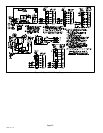
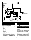
UNIT COMPONENTS
IMPORTANT
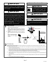
Some scroll compressor have internal vacuum protector
that will unload scrolls when suction pressure goes
below 20 psig. A hissing sound will be heard when the
compressor is running unloaded. Protector will reset
when low pressure in system is raised above 40 psig. DO
NOT REPLACE COMPRESSOR.
The outdoor unit and indoor blower cycle on demand from
the room thermostat. When the thermostat blower switch
is in the ON position, the indoor blower operates
continuously.
High Pressure Switch (S4)
XC16 units are equipped with a high-pressure switch that
is located in the liquid line of the compressor as illustrated
in Unit Dimensions on page 2. The switch is a Single Pole,
Single Throw (SPST), manual−reset switch with red cap
that is normally closed and removes power from the
compressor when discharge pressure rises above factory
setting at 590 + 10 psi.
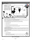
Low Pressure Switch (S87)
XC16 units are also equipped with a low pressure switch
that is located in the vapor line of the compressor. The
switch (SPST, auto−reset, normally closed) removes
power from the compressor when vapor line pressure
drops below factory setting at 40 + 5 psi.
Crankcase Thermostat (S40) (−048 and −060 Units
Only)
Compressor in the XC16−048 and −060 units are equipped
with a 70 watt, belly band type crankcase heater. HR1
prevents liquid from accumulating in the compressor. HR1
is controlled by a thermostat located on the liquid line.
When liquid line temperature drops below 50° F the
thermostat closes energizing HR1. The thermostat will
open, de−energizing HR1 once liquid line temperature
reaches 70° F .
Liquid Line Filter Drier
A filter drier is factory-installed as illustrated in Unit
Dimensions on page 2, with each XC16 unit to ensure a
clean, moisture−free system. A replacement filter drier is
available from Lennox. Refer to Lennox Repair Part
Program.
Maintenance
DEALER
Maintenance and service must be performed by a qualified
installer or service agency. At the beginning of each
cooling season, the system should be checked as follows:
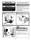
Outdoor Unit
1. Clean and inspect the outdoor coil. The coil may be
flushed with a water hose. Ensure the power is turned
off before you clean the coil.
2. Outdoor fan motor is prelubricated and sealed. No
further lubrication is needed.
3. Visually inspect connecting lines and coils for
evidence of oil leaks.
4. Check wiring for loose connections.
5. Check for correct voltage at the unit (with the unit
operating).
6. Check amp−draw outdoor fan motor.
UNIT NAMEPLATE: _________ ACTUAL: __________
NOTE − If owner reports insufficient cooling, the unit should
be gauged and refrigerant charge checked.
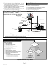
Outdoor Coil
It may be necessary to flush the outdoor coil more
frequently if it is exposed to substances which are
corrosive or which block airflow across the coil (e.g., pet
urine, cottonwood seeds, fertilizers, fluids that may contain
high levels of corrosive chemicals such as salts)
S Outdoor Coil Ċ The outdoor coil may be flushed with
a water hose.
S Outdoor Coil (Sea Coast) Ċ Moist air in ocean
locations can carry salt, which is corrosive to most
metal. Units that are located near the ocean require
frequent inspections and maintenance. These
inspections will determine the necessary need to wash
the unit including the outdoor coil. Consult your
installing contractor for proper intervals/procedures
for your geographic area or service contract.
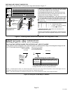
INDOOR UNIT
1. Clean or change filters.
2. Adjust blower speed for cooling. Measure the pressure
drop over the coil to determine the correct blower CFM.
Refer to the unit information service manual for pressure
drop tables and procedure.
3. Check blower drive belt for wear and proper tension.
4. Check all wiring for loose connections
5. Check for correct voltage at unit (blower operating).
6. Check amp−draw on blower motor.
UNIT NAMEPLATE: _________ ACTUAL: __________
INDOOR COIL
1. Clean coil, if necessary.
2. Check connecting lines and coils for signs of oil leaks.
3. Check condensate line and clean, if necessary.
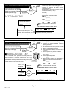
TWO−STAGE COMPRESSOR CHECKS
Use the checklist procedure on page 28, to verify part-load
and full-load capacity operation of two-stage modulation
compressors.
IMPORTANT
This performance check is ONLY valid on systems that
have clean indoor and outdoor coils, proper airflow over
coils, and correct system refrigerant charge. All
components in the system must be functioning proper to
correctly perform compressor modulation operational
check. (Accurate measurements are critical to this test
as indoor system loading and outdoor ambient can affect
variations between low and high capacity readings).
Tools Required
S Refrigeration gauge set