


Page 19
XC16 SERIES
IMPORTANT
Use a thermocouple or thermistor electronic vacuum
gauge that is calibrated in microns. Use an instrument
capable of accurately measuring down to 50 microns.
WARNING
Danger of Equipment Damage. Avoid deep vacuum
operation. Do not use compressors to evacuate a
system. Extremely low vacuums can cause internal
arcing and compressor failure. Damage caused by
deep vacuum operation will void warranty.
Evacuating the system of non−condensables is critical for
proper operation of the unit. Non−condensables are
defined as any gas that will not condense under
temperatures and pressures present during operation of
an air conditioning system. Non−condensables and water
suction combine with refrigerant to produce substances
that corrode copper piping and compressor parts.
Electrical
In the U.S.A., wiring must conform with current local codes
and the current National Electric Code (NEC). In Canada,
wiring must conform with current local codes and the current
Canadian Electrical Code (CEC).
Refer to the furnace or air handler installation instructions
for additional wiring application diagrams and refer to unit
nameplate for minimum circuit ampacity and maximum
overcurrent protection size.
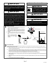
24VAC TRANSFORMER
Use the transformer provided with the furnace or air
handler for low-voltage control power (24VAC − 40 VA
minimum)
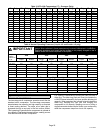
Refer to the unit nameplate for minimum circuit ampacity, and
maximum fuse or circuit breaker (HACR per NEC). Install power
wiring and properly sized disconnect switch.
NOTE Ċ Units are approved for use only with copper conductors.
Ground unit at disconnect switch or to an earth ground.
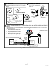
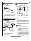
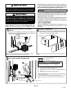
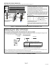
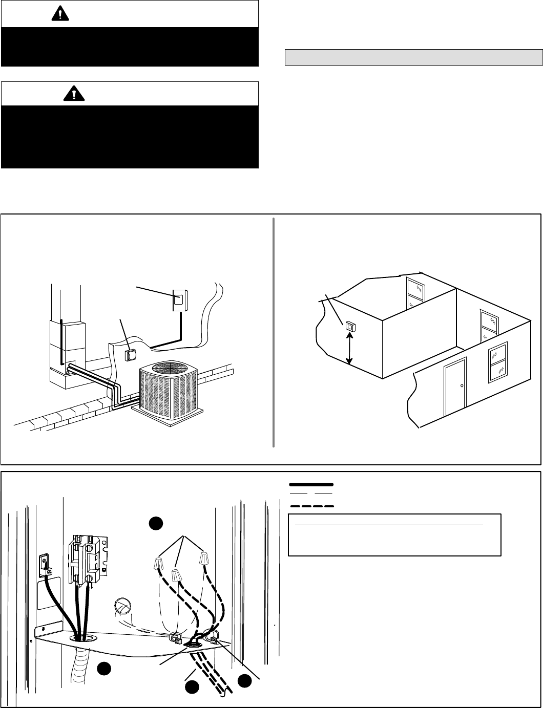
SIZE CIRCUIT AND INSTALL DISCONNECT
SWITCH
1
NOTE Ċ 24VAC, Class II circuit connections are made in the control
panel.
Install room thermostat (ordered separately) on an inside wall
approximately in the center of the conditioned area and 5 feet
(1.5m) from the floor. It should not be installed on an outside wall
or where it can be affected by sunlight or drafts.
THERMOSTAT
5 FEET
(1.5M)
INSTALL THERMOSTAT
2
DISCONNECT
SWITCH
MAIN FUSE
BOX/BREAKER
PANEL
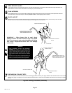
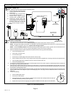
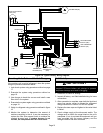
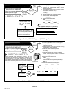
A Run 24VAC control wires through cutout with grommet.
B Run 24VAC control wires through wire tie.
C Make 24VAC control wire connections using field provided wire
nuts.
D Tighten wire tie to security 24V control wiring.
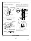
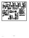
HIGH VOLTAGE FIELD WIRING
LOW VOLTAGE (24V) FIELD WIRING
FACTORY WIRING
CUTOUT WITH
GROMMET
NOTE − FOR PROPER VOLTAGES, SELECT THERMOSTAT WIRE (CONTROL WIRES)
GAUGE PER TABLE ABOVE.
WIRE RUN LENGTH AWG# INSULATION TYPE
LESS THAN 100’ (30 METERS) 18 TEMPERATURE RATING
MORE THAN 100’ (30 METERS) 16 35ºC MINIMUM.
WIRE NUTS
BLACK
24V CONTROL WIRES
YELLOW
TIGHTEN WIRE TIE
UNIT LOW VOLTAGE CONNECTIONS
NOTE − DO NOT BUNDLE ANY EXCESS 24VAC CONTROL WIRES INSIDE CONTROL
BOX.
NOTE − WIRE TIE PROVIDES LOW VOLTAGE WIRE STRAIN RELIEF AND TO MAINTAIN
SEPARATION OF FIELD INSTALLED LOW AND HIGH VOLTAGE CIRCUITS.
A
B
C
D
3
BLUE