


Page 25
XC16 SERIES
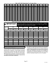
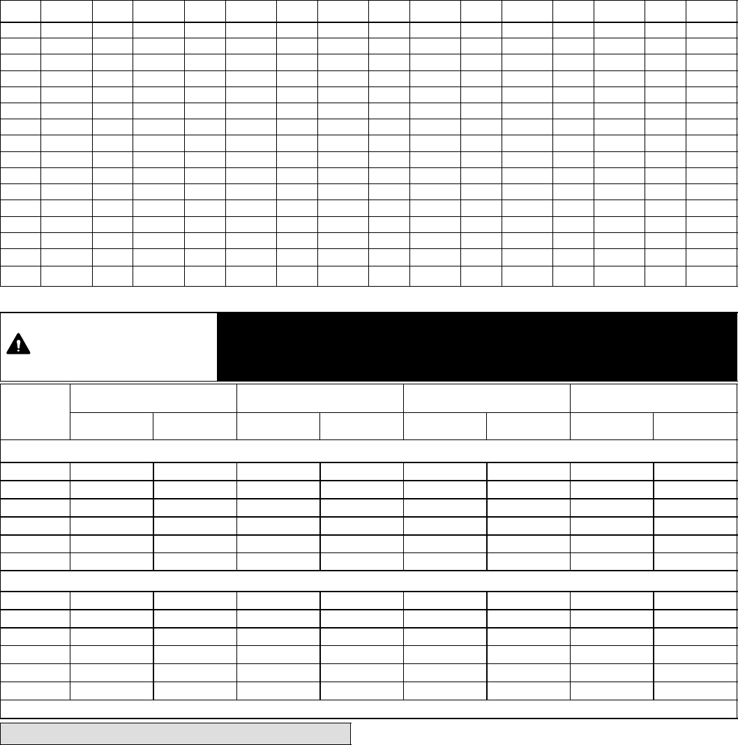
Table 3. HFC−410A Temperature (°F) − Pressure (Psig)
°F
Psig °F Psig °F Psig °F Psig °F Psig °F Psig °F Psig °F Psig
32 100.8 48 137.1 63 178.5 79 231.6 94 290.8 110 365.0
125 445.9
141 545.6
33 102.9 49 139.6 64 181.6 80 235.3 95 295.1 111 370.0 126 451.8 142 552.3
34 105.0 50 142.2 65 184.3 81 239.0 96 299.4 112 375.1 127 457.6 143 559.1
35 107.1 51 144.8 66 187.7 82 242.7 97 303.8 113 380.2 128 463.5 144 565.9
36 109.2 52 147.4 67 190.9 83 246.5 98 308.2 114 385.4 129 469.5 145 572.8
37 111.4 53 150.1 68 194.1 84 250.3 99 312.7 115 390.7 130 475.6 146 579.8
38 113.6 54 152.8 69 197.3 85 254.1 100 317.2 116 396.0 131 481.6 147 586.8
39 115.8 55 155.5 70 200.6 86 258.0 101 321.8 117 401.3 132 487.8 148 593.8
40 118.0 56 158.2 71 203.9 87 262.0 102 326.4 118 406.7 133 494.0 149 601.0
41 120.3 57 161.0 72 207.2 88 266.0 103 331.0 119 412.2 134 500.2 150 608.1
42 122.6 58 163.9 73 210.6 89 270.0 104 335.7 120 417.7 135 506.5 151 615.4
43 125.0 59 166.7 74 214.0 90 274.1 105 340.5 121 423.2 136 512.9 152 622.7
44 127.3 60 169.6 75 217.4 91 278.2 106 345.3 122 428.8 137 519.3 153 630.1
45 129.7 61 172.6 76 220.9 92 282.3 107 350.1 123 434.5 138 525.8 154 637.5
46 132.2 62 175.4 77 224.4 93 286.5 108 355.0 124 440.2 139 532.4 155 645.0
47 134.6 78 228.0 109 360.0 140 539.0
Table 4. Normal Operating Pressures (Liquid +10 and Suction +5 psig)
IMPORTANT
Use this table to perform maintenance checks; it is not a procedure for charging the
system. Minor variations in these pressures may be due to differences in installations.
Significant deviations could mean that the system is not properly charged or that a
problem exists with some component in the system.
Temp. of air
entering
outdoor coil
5F (5C)
−024 −036 −048 −060
Liquid Suction Liquid Suction Liquid Suction Liquid Suction
First Stage (Low Capacity)
65 (18.3) 215 144 226 142 224 142 215 136
75 (23.9) 247 146 261 144 258 144 250 139
85 (29.4) 288 148 304 145 299 146 291 142
95 (35.0) 332 151 352 147 345 148 337 144
105 (40.6) 381 153 405 150 395 150 388 146
115 (46.1) 435 155 460 150 450 153 444 148
Second Stage (High Capacity)
65 (18.3) 225 140 228 144 235 135 220 130
75 (23.9) 258 142 262 146 269 137 256 133
85 (29.4) 301 144 306 148 313 139 299 136
95 (35.0) 346 146 353 150 361 141 347 138
105 (40.6) 397 149 405 151 412 143 402 141
115 (46.1) 452 151 462 154 471 146 462 143
*These are typical pressures only. Indoor indoor match up, indoor air quality, and indoor load will cause the pressures to vary.
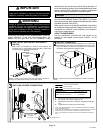
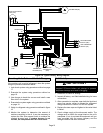
System Operation
TWO−STAGE COMPRESSOR
The two−stage scroll compressor operates much like the
standard scroll compressor. The two−stage compressor
steps between low capacity and high capacity as required
to meet cooling demand. The steps occur when gas is
bypassed through a vent port in the first suction pocket.
This bypassing of gas allows the compressor to operate at
low capacity if thermostat demand allows, creating a more
cost effective and efficient compressor.
Full capacity is achieved by blocking the vent port with a
slider ring. The slider ring (vent port cover) is controlled by
a 24VDC internal solenoid in the open position allowing low
capacity. When energized the internal solenoid closes the
slider ring, blocking the vent port and bringing the
compressor to full capacity. Stepping can occur during a
single thermostat demand as the motor runs continuously
while the compressor steps from low to full capacity.