


506920−01 09/12
Page 68
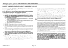
Setting up typical systemsĊAIR HANDLER & AIR CONDITIONER
icomfortt−enabled Air Handler & icomfortt−enabled Air Conditioner
An icomfort−enabled air handler (CBX32MV or CBX40UHV) with an icom-
fort−enabled air conditioner (XC17 or XC21 only).
NOTE − IMPORTANT! Be sure to configure the air handler control so that
heat strips (if used) information will be detected by the icomfort thermostat.
This must be done prior to powering up the system and thermostat.
1. Configure air handler control (AHC) for auxiliary heat strips if used.
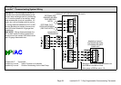
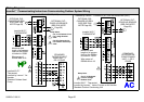
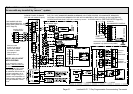
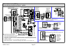
2. WiringĊSee Communicating System Wiring diagram on Page 59
and Optional Accessories Wiring (Page 61) for any accessories be-
ing installed with the system.
D 4−conductor thermostat wire from the icomfort Wi-Fit thermostat
to the air handler (R, i+, i−, C)
D 4−conductor thermostat wire from the air handler terminal strip to
the icomfort−enabled AC (R, i+, i−, C)
D Wiring as required for accessories
3. DO NOT cut any option link on air handler control.
4. After the entire system is wired, power up the system; the icomfort Wi-
Fit thermostat will check the system for installed communication de-
vices.
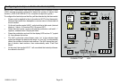
5. On the thermostat, go past the Add or remove non−communicating
equipment" to the To adjust a setting" screen.
6. Use the arrows to select Air Handler" from system devices list; press
edit. From this Air Handler screen you will have access to the various
airflow settings. Set the system air volumes according the needs of the
home. When you change certain settings, the system will prompt you
to please view and save all red settings". Use the arrows to select the
red settings and press edit. Either make changes or not, but press
save either way. The red settings will go away after pressing save.
When all CFM settings are complete, press the back button. Press
next step to advance to the tests button.
7. Test the system operation and confirm the system is electrically ener-
gized and operational. Particularly, test the heat strips (when used) to
insure the auxiliary stages operate as designed. Press done.
8. Exit the installer setup mode by selecting the EXIT button.
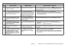
TIPS
S If the thermostat System Setting" does not offer a choice for emerg.
heat" and or the electric heat will not function; the electric heat has not
been configured. Configure the electric heat as described on Page 64,
or for complete detail, see the Air Handler installation instructions. Re-
configure the icomfort system by entering the installer program and se-
lecting the setup button and following the prompts.
S An outdoor temperature sensor is provided in an icomfort−enabled air
conditioning unit. To display the outdoor temperature on the home
screen of the thermostat, you must turn on (or off) the Outdoor Temp
Display". From the Home screen, press press for more area and se-
lect the HELP icon. Press the user preferences box and scroll down
to Outdoor Temp Display". Press the modify button and use the up/
down arrows to select On (or Off) and then press the save button.
Press done to return to the Home screen.
S Turn the Indoor Humidity Display on and off in a similar manner as
above.