


506052−01 11/09
Page 4
icomfortt Technical Description
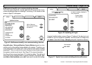
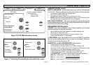
The 24VAC icomfortt thermostat stores system parameters and set-
tings in a nonvolatile memory (i.e., it retains data when electrical power
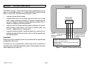
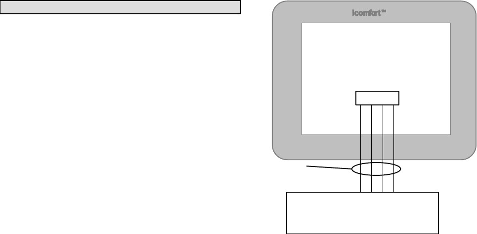
fails or is turned off). The thermostat (see figure 1) also:
S includes on-board help screens,
S supports heat pumps or non−heat pump units, with up to 4 stage
heat / 2 stage compressor operation. (2 stages of heat pump heat-
ing and 2 stages of auxiliary backup heat are provided. Also, 2
stages of emergency heat are provided),
S supports Indoor Air Quality with time-based notification of consum-
ables including media filters, UVC bulbs, humidifier pads, and
PureAirt catalyst service / replacement,
S supports variable capacity / multistage heat/cool, universal com-
patibility (gas/electric/heat pump/ac), and is dual fuel capable with
two balance points.
Important
Always use correct software version as recommended for replacement
configuration (discovery).
Connections to non communication outdoor units and all accessories is
described in the Quick−Start Installation guide. (Wiring diagrams are also
shown beginning on Page 36.)
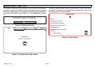
Thermostat
connections
RSBUS
Minimum wire size is
18 gauge
icomfortt Outdoor Units Control
icomfortt Furnace Control
icomfortt Air Handler Control
External Sensors − outdoor temperature and humidity
Humidify control
Dehumidify control
R I+ I − C
Maximum total length
of all connections on
the RSBus is limited
to 1500ft.
Figure 1. icomfort thermostat system