


Page 9
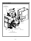
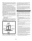
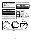
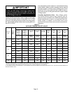
FIGURE 8
RIGID LEG
remove shipping bolt and washer
ML193DF09048C BLOWER MOTOR
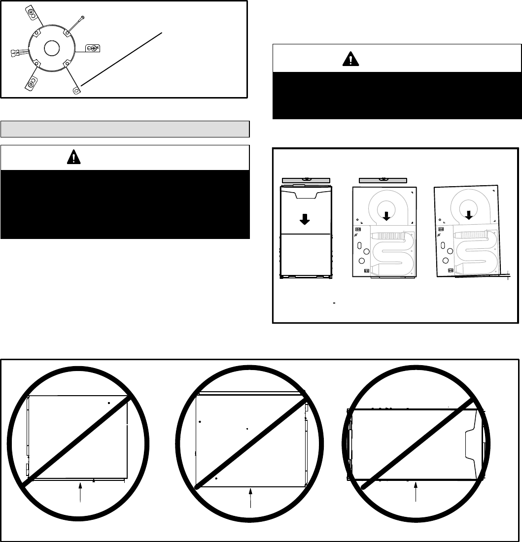
Installation − Setting Equipment
WARNING
Do not install the furnace on its front, back or in the
horizontal position. See figure 10. Do not connect the
return air ducts to the back of the furnace. Doing so
will adversely affect the operation of the safety con-
trol devices, which could result in personal injury or
death.
Select a location that allows for the required clearances
that are listed on the unit nameplate. Also consider gas
supply connections, electrical supply, vent connection,
condensate trap and drain connections, and installation
and service clearances [24 inches (610 mm) at unit
front]. The unit must be level from side to side. Unit may
be positioned from level to 1/2" toward the front to aid in
draining. See figure 9.
Allow for clearances to combustible materials as indicated
on the unit nameplate. Minimum clearances for closet or al-
cove installations are shown in figure 11.
WARNING
Blower access panel must be securely in place when
blower and burners are operating. Gas fumes, which
could contain carbon monoxide, can be drawn into
living space resulting in personal injury or death.
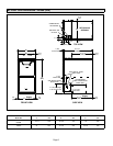
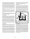
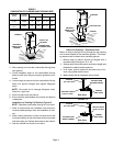
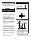
FIGURE 9
SETTING EQUIPMENT
FRONT VIEW SIDE VIEW
AIR FLOW
AIR FLOW
1/2"
max.
AIR FLOW
SIDE VIEW
Unit must be level side−to−side. Unit may be positioned
from level to 1/2" toward the front to aid in draining.
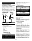
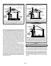
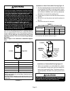
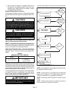
FIGURE 10
Front
Back
Horizontal
NOTE − Do not install the furnace on its front, back or in the horizontal position