


Page 12
Filters
This unit is not equipped with a filter or rack. A field−pro-
vided filter is required for the unit to operate properly. Table
3 lists recommended filter size.
A filter must be in place whenever the unit is operating.
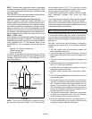
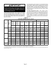
TABLE 3
Furnace
Cabinet Width
Filter Size
16 x 25 x 1 (1)
17−1/2"
21"
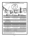
Duct System
Use industry-approved standards to size and install the
supply and return air duct system. Refer to ACCA Manual
D. This will result in a quiet and low-static system that has
uniform air distribution.
NOTE − This furnace is not certified for operation in heating
mode (indoor blower operating at selected heating speed)
with an external static pressure which exceeds 0.5 inches
w.c. Operation at these conditions may result in improper
limit operation.
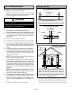
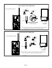
Supply Air Plenum
If the furnace is installed without a cooling coil, a removable
access panel should be installed in the supply air duct. The
access panel should be large enough to permit inspection
of the heat exchanger. The furnace access panel must al-
ways be in place when the furnace is operating and it must
not allow leaks into the supply air duct system.
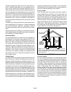
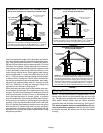
Return Air Plenum
NOTE − Return air must not be drawn from a room
where this furnace, or any other gas−fueled appliance
(i.e., water heater), or carbon monoxide−producing de-
vice (i.e., wood fireplace) is installed.
When return air is drawn from a room, a negative pres-
sure is created in the room. If a gas appliance is operating
in a room with negative pressure, the flue products can
be pulled back down the vent pipe and into the room. This
reverse flow of the flue gas may result in incomplete com-
bustion and the formation of carbon monoxide gas. This
raw gas or toxic fumes might then be distributed through-
out the house by the furnace duct system.
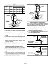
Use fiberglass sealing strips, caulking, or equivalent seal-
ing method between the plenum and the furnace cabinet to
ensure a tight seal. If a filter is installed, size the return air
duct to fit the filter frame.
Pipe & Fittings Specifications
All pipe, fittings, primer and solvent cement must conform
with American National Standard Institute and the Ameri-
can Society for Testing and Materials (ANSI/ASTM) stan-
dards. The solvent shall be free flowing and contain no
lumps, undissolved particles or any foreign matter that ad-
versely affects the joint strength or chemical resistance of
the cement. The cement shall show no gelation, stratifica-
tion, or separation that cannot be removed by stirring. Re-
fer to the table 4 below for approved piping and fitting ma-
terials.
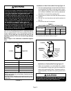
CAUTION
Solvent cements for plastic pipe are flammable liq-
uids and should be kept away from all sources of
ignition. Do not use excessive amounts of solvent
cement when making joints. Good ventilation should
be maintained to reduce fire hazard and to minimize
breathing of solvent vapors. Avoid contact of cement
with skin and eyes.
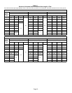
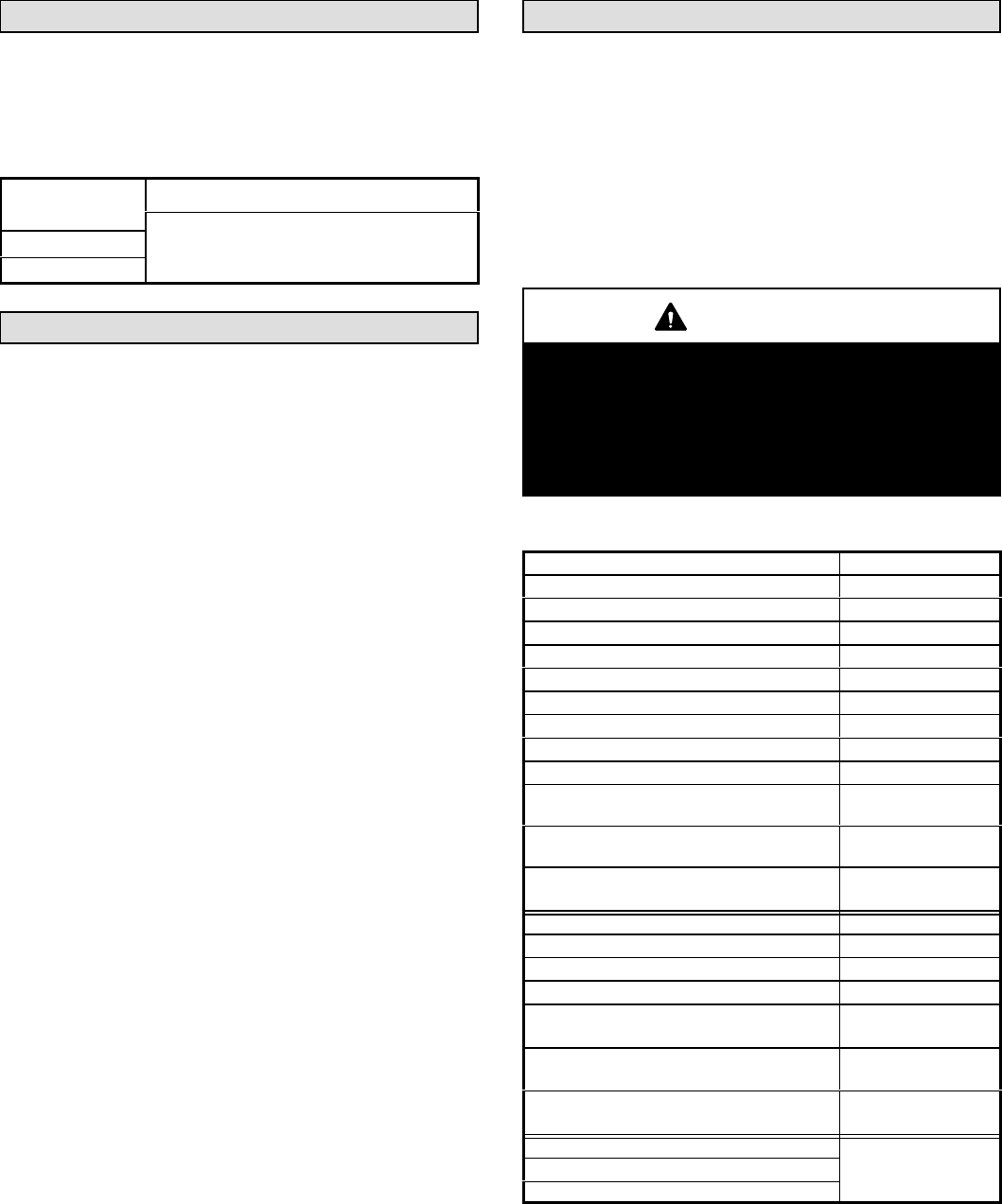
TABLE 4
PIPING AND FITTINGS SPECIFICATIONS
Schedule 40 PVC (Pipe) D1785
Schedule 40 PVC (Cellular Core Pipe) F891
Schedule 40 PVC (Fittings) D2466
Schedule 40 CPVC (Pipe) F441
Schedule 40 CPVC (Fittings) F438
SDR−21 PVC or SDR−26 PVC (Pipe) D2241
SDR−21 CPVC or SDR−26 CPVC (Pipe) F442
Schedule 40 ABS Cellular Core DWV (Pipe) F628
Schedule 40 ABS (Pipe) D1527
Schedule 40 ABS (Fittings) D2468
ABS−DWV (Drain Waste & Vent)
(Pipe & Fittings)
D2661
PVC−DWV (Drain Waste & Vent)
Pipe & Fittings)
D2665
PRIMER & SOLVENT CEMENT
ASTM
SPECIFICATION
PVC & CPVC Primer F656
PVC Solvent Cement D2564
CPVC Solvent Cement F493
ABS Solvent Cement D2235
PVC/CPVC/ABS All Purpose Cement For
Fittings & Pipe of the same material
D2564, D2235, F493
ABS to PVC or CPVC Transition Solvent
Cement
D3138
CANADA PIPE & FITTING & SOLVENT
CEMENT
MARKING
PVC & CPVC Pipe and Fittings
ULCS636
PVC & CPVC Solvent Cement
ABS to PVC or CPVC Transition Cement