


Page 28
5 − If unit will be started immediately upon completion of
installation, prime trap per procedure outlined in Unit
Start−Up section.
Condensate line must slope downward away from the
trap to drain. If drain level is above condensate trap,
condensate pump must be used. Condensate drain
line should be routed within the conditioned space to
avoid freezing of condensate and blockage of drain
line. If this is not possible, a heat cable kit may be used
on the condensate trap and line. Heat cable kit is avail-
able from Lennox in various lengths; 6 ft. (1.8m) − kit
no. 26K68; 24 ft. (7.3m) − kit no. 26K69; and 50 ft.
(15.2m) − kit no. 26K70.
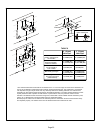
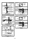
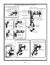
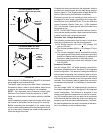
FIGURE 43
CONDENSATE TRAP LOCATION
(shown with right side exit of condensation)
5’ max.
to drain
Field Provided Vent
min. 1" Above
Condensate Drain
1" min.
Trap can be installed a
maximum of 5 ft. from furnace.
(*PVC Only)
*Piping from furnace must slope down a minimum of
1/4" per ft. toward trap.
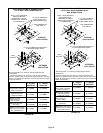
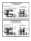
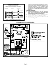
FIGURE 44
ML193DF with Evaporator Coil
Drain
Condensate trap and
evaporator coil must drain
separately as shown.
Field−Provided Vent
CAUTION
Do not use copper tubing or existing copper
condensate lines for drain line.
CAUTION
A separate drain line must be run to the drain
from the condensate trap to ensure proper
drainage and pressure switch operation. DO
NOT connect the condensate trap drain into the
drain line from the evaporator coil.