


Page 27
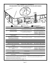
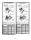
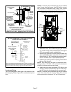
FIGURE 40
12" (305mm)
ABOVE GRADE OR
AVERAGE SNOW
ACCUMULATION
UNCONDITIONED
SPACE
1/2" (13mm) FOAM
INSULATION
1/2" (13mm) FOAM
INSULATION IN
UNCONDITIONED
SPACE
*WALL SUPPORT
OUTSIDE WALL
SIZE TER-
MINATION
PIPE PER
TABLE 8.
FIELD−PROVIDED
REDUCER MAY BE
REQUIRED TO
ADAPT LARGER
VENT PIPE SIZE TO
TERMINATION
*Use wall support every 24" (610). Use
two supports if extension is greater
than 24" but less than 48".
12" (305mm) MAX. for 2" (51mm)
20" (508mm) MAX. for 3" (76mm)
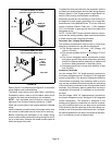
NON−DIRECT VENT FIELD SUPPLIED WALL TERMINATION EX-
TENDED OR (15F74) WALL TERMINATION VENT PIPE EXTENDED
6" (152mm)
Max
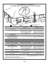
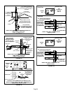
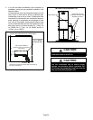
NOTE − Do not discharge exhaust gases directly into any chimney or vent stack. If ver-
tical discharge through an existing unused chimney or stack is required, insert piping
inside chimney until the pipe open end is above top of chimney and terminate as illus-
trated. In any exterior portion of chimney, the exhaust vent must be insulated.
FIGURE 41
3" − 8"
(76mm−
203mm)
3" − 8"
(76mm−
203mm)
STRAIGHT−CUT OR
ANGLE−CUT IN DIRECTION
OF ROOF SLOPE
EXHAUST VENT
1/2" (13mm)
WEATHERPROOF
INSULATION
SHOULDER OF FITTINGS
PROVIDE SUPPORT
OF PIPE ON TOP PLATE
EXTERIOR
PORTION OF
CHIMNEY
INSULATE
TO FORM
SEAL
SHEET
METAL TOP
PLATE
SIZE TERMINATION
PIPE PER TABLE 8.
ML193DF NON−DIRECT VENT APPLICATION
USING EXISTING CHIMNEY
Minimum 12" (305MM)
above chimney top
plate or average snow
accumulation
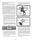
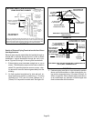
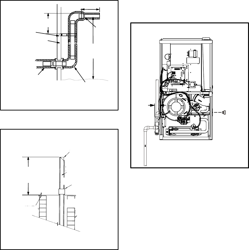
Condensate Piping
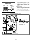
This unit is designed for either right- or left-side exit of con-
densate piping. Refer to figure 42 for condensate trap loca-
tions.
NOTE − If necessary the condensate trap may be installed
up to 5´ away from the furnace. Use PVC pipe to connect
trap to furnace condensate outlet. Piping from furnace
must slope down a minimum of 1/4" per ft. toward trap.
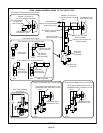
FIGURE 42
CONDENSATE TRAP AND PLUG LOCATIONS
Trap
(same on
right side)
Plug
(same on left
side)
1−1/2 in.
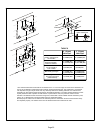
1 − Determine which side condensate piping will exit the
unit, location of trap, field−provided fittings and length of
PVC pipe required to reach available drain.
2 − Remove plug (figure 42) from the cold end header box
at the appropriate location on the side of the unit. Install
field−provided 1/2" NPT male fitting into cold end head-
er box. Use teflon tape or appropriate pipe dope.
3 − Install the cap over the clean out opening at the base of
the trap. See figure 45.
NOTE − Vinyl tubing may be used for condensate drain.
Tubing must be 1−1/4" OD X 1" ID and should be attached to
the drain on the trap using a hose clamp.
4 − Install drain trap using appropriate PVC fittings, glue
all joints. Glue the provided drain trap as shown in fig-
ure 45. Route the condensate line to an open drain.
NOTE − If necessary the condensate trap may be installed
up to 5 feet away from the furnace. Piping from furnace
must slope down a minimum of 1/4" per ft. toward trap.