


Page 8
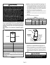
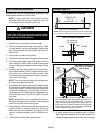
FIGURE 5
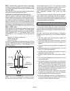
EQUIPMENT IN CONFINED SPACE − ALL AIR FROM OUTSIDE
(Inlet Air from Crawl Space and Outlet Air to Ventilated Attic)
NOTE−The inlet and outlet air openings shall each have a free area
of at least one square inch per 4,000 Btu (645mm
2
per 1.17kW) per
hour of the total input rating of all equipment in the enclosure.
OUTLET
AIR
INLET
AIR
VENTILATION
LOUVERS
(For unheated
crawl space)
ROOF TERMINATED
EXHAUST PIPE
VENTILATION LOUVERS
(Each end of attic)
SIDE WALL
TERMINATED
EXHAUST PIPE
(ALTERNATE
LOCATION)
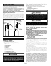
If air from outside is brought in for combustion and ventila-
tion, the confined space must have two permanent open-
ings. One opening shall be within 12 inches (305 mm) of
the top of the enclosure and one opening within 12 inches
(305 mm) of the bottom. These openings must communi-
cate directly or by ducts with the outdoors or spaces (crawl
or attic) that freely communicate with the outdoors or indi-
rectly through vertical ducts. Each opening shall have a
minimum free area of 1 square inch (645 mm
2
) per 4,000
Btu (1.17 kW) per hour of total input rating of all equipment
in the enclosure. See figures 5 and 6. When communicat-
ing with the outdoors through horizontal ducts, each open-
ing shall have a minimum free area of 1 square inch (645
mm
2
) per 2,000 Btu (.56 kW) per total input rating of all
equipment in the enclosure. See figure 7.
When ducts are used, they shall be of the same cross−sec-
tional area as the free area of the openings to which they
connect. The minimum dimension of rectangular air ducts
shall be no less than 3 inches (75 mm). In calculating free
area, the blocking effect of louvers, grilles, or screens
must be considered. If the design and free area of protec-
tive covering is not known for calculating the size opening
required, it may be assumed that wood louvers will have
20 to 25 percent free area and metal louvers and grilles
will have 60 to 75 percent free area. Louvers and grilles
must be fixed in the open position or interlocked with the
equipment so that they are opened automatically during
equipment operation.
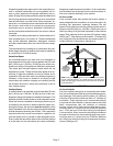
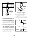
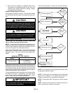
FIGURE 6
EQUIPMENT IN CONFINED SPACE − ALL AIR FROM OUTSIDE
(All Air Through Ventilated Attic)
NOTE−The inlet and outlet air openings shall each have a free area of
at least one square inch per 4,000 Btu (645mm
2
per 1.17kW) per
hour of the total input rating of all equipment in the enclosure.
OUTLET
AIR
VENTILATION LOUVERS
(Each end of attic)
INLET AIR
(Ends 12" above
bottom)
ROOF TERMINATED
EXHAUST PIPE
SIDE WALL
TERMINATED
EXHAUST PIPE
(ALTERNATE
LOCATION)
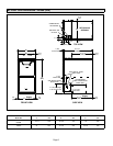
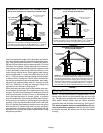
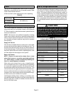
FIGURE 7
EQUIPMENT IN CONFINED SPACE −
ALL AIR FROM OUTSIDE
OUTLET AIR
INLET AIR
NOTE−Each air duct opening shall have a free area of at least one
square inch per 2,000 Btu (645mm
2
per .59kW) per hour of the total
input rating of all equipment in the enclosure. If the equipment room
is located against an outside wall and the air openings communi-
cate directly with the outdoors, each opening shall have a free area
of at least 1 square inch per 4,000 Btu (645mm
2
per 1.17kW) per
hour of the total input rating of all other equipment in the enclosure.
ROOF TERMINATED
EXHAUST PIPE
SIDE WALL
TERMINATED
EXHAUST PIPE
(ALTERNATE
LOCATION)
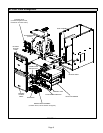
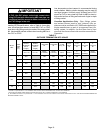
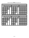
Shipping Bolt Removal
NOTE − The ML193DF09048C is equipped with a 1/2 hp
blower motor which has three flexible legs and one rigid
leg. The rigid leg is equipped with a shipping bolt and a flat
white plastic washer (rather than the rubber mounting
grommet used with a flexible mounting leg). See figure 8.
The bolt and washer must be removed before the fur-
nace is placed into operation. After the bolt and washer
have been removed, the rigid leg will not touch the blower
housing.