


Page 18
Intake Piping
The ML193DF furnace may be installed in either direct
vent or non−direct vent applications. In non−direct vent
applications, when intake air will be drawn into the furnace
from the surrounding space, the indoor air quality must be
considered. Guidelines listed in Combustion, Dilution and
Ventilation Air section must be followed.
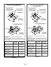
Follow the next two steps when installing the unit in Direct
Vent applications, where combustion air is taken from
outdoors and flue gases are discharged outdoors. The
provided air intake screen must not be used in direct
vent applications (outdoors).
1 − Use cement to secure the intake pipe to the inlet air
connector.
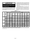
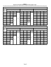
2 − Route piping to outside of structure. Continue with
installation following instructions given in general
guide lines for piping terminations and intake and ex-
haust piping terminations for direct vent sections. Re-
fer to table 7 for pipe sizes.
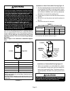
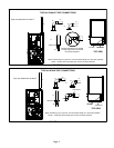
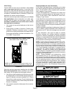
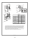
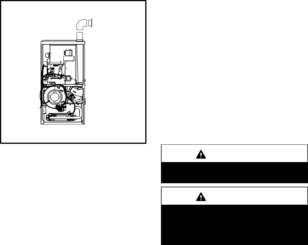
FIGURE 22
TYPICAL AIR INTAKE PIPE CONNECTIONS
NON−DIRECT VENT APPLICATIONS
AIR
INTAKE
SCREEN
(Provided)
NOTE − Air intake screen and elbow may be rotated, so that
screen may be positioned to face forward or to either side.
Follow the next two steps when installing the unit in Non-
Direct Vent applications where combustion air is taken
from indoors and flue gases are discharged outdoors.
1 − Use field−provided materials and the factory−provided
air intake screen to route the intake piping as shown in
figure 22. Maintain a minimum clearance of 3" (76mm)
around the air intake opening. The air intake opening
(with the protective screen) should always be directed
forward, or sideways.
2 − Use cement to secure the intake pipe to the connector,
if desired.
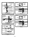
General Guidelines for Vent Terminations
In Non-Direct Vent applications, combustion air is taken
from indoors and the flue gases are discharged to the out-
doors. The ML193DF is then classified as a non-direct
vent, Category IV gas furnace.
In Direct Vent applications, combustion air is taken from
outdoors and the flue gases are discharged to the out-
doors. The ML193DF is then classified as a direct vent,
Category IV gas furnace.
In both Non-Direct Vent and Direct Vent applications, the
vent termination is limited by local building codes. In the
absence of local codes, refer to the current National Fuel
Gas Code ANSI Z223−1/NFPA 54 in U.S.A., and current
CSA−B149 Natural Gas and Propane Installation Codes in
Canada for details.
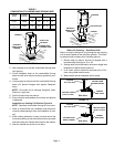
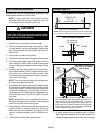
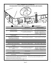
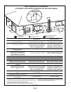
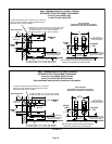
Position termination according to location given in figure 23
or 24. In addition, position termination so it is free from any
obstructions and 12" above the average snow accumula-
tion.
At vent termination, care must be taken to maintain
protective coatings over building materials (prolonged
exposure to exhaust condensate can destroy protective
coatings). It is recommended that the exhaust outlet not be
located within 6 feet (1.8m) of a condensing unit because
the condensate can damage the painted coating.
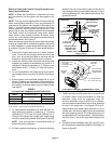
NOTE − If winter design temperature is below 32°F (0°C),
exhaust piping should be insulated with 1/2" (13mm), Ar-
maflex or equivalent when run through unheated space.
Do not leave any surface area of exhaust pipe open to out-
side air; exterior exhaust pipe should be insulated with
1/2" (13mm) Armaflex or equivalent. In extreme cold cli-
mate areas, 3/4" (19mm) Armaflex or equivalent may be
necessary. Insulation on outside runs of exhaust pipe
must be painted or wrapped to protect insulation from de-
terioration. Exhaust pipe insulation may not be necessary
in some specific applications.
NOTE − During extremely cold temperatures, below
approximately 20°F (6.7°C), units with long runs of vent
pipe through unconditioned space, even when insulated,
may form ice in the exhaust termination that prevents the
unit from operating properly. Longer run times of at least 5
minutes will alleviate most icing problems. Also, a heating
cable may be installed on exhaust piping and termination
to prevent freeze−ups. Heating cable installation kit is
available from Lennox. See Condensate Piping section
for part numbers.
IMPORTANT
Do not use screens or perforated metal in exhaust
terminations. Doing so will cause freeze−ups and
may block the terminations.
IMPORTANT
For Canadian Installations Only:
In accordance to CSA International B149 installation
codes, the minimum allowed distance between the
combustion air intake inlet and the exhaust outlet of
other appliances shall not be less than 12 inches
(305mm).