


Page 38
Gas Pressure Adjustment
Gas Flow (Approximate)
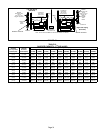
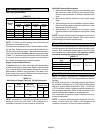
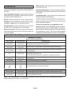
TABLE 11
GAS METER CLOCKING CHART
ML193
Unit
Seconds for One Revolution
Natural LP
1 cu ft
Dial
2 cu ft
Dial
1 cu ft
Dial
2 cu ft
DIAL
−045 80 160 200 400
−070 55 110 136 272
−090 41 82 102 204
−110 33 66 82 164
Natural−1000 btu/cu ft LP−2500 btu/cu ft
NOTE − To obtain accurate reading, shut off all other gas
appliances connected to meter.
Furnace should operate at least 5 minutes before check-
ing gas flow. Determine time in seconds for two revolu-
tions of gas through the meter. (Two revolutions assures a
more accurate time). Divide by two and compare to time
in table 11. If manifold pressure matches table 12 and rate
is incorrect, check gas orifices for proper size and restric-
tion. Remove temporary gas meter if installed.
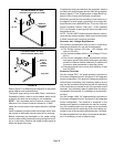
Supply Pressure Measurement
A threaded plug on the inlet side of the gas valve provides
access to the supply pressure tap. Remove the threaded
plug, install a field−provided barbed fitting and connect a
manometer to measure supply pressure. See table 12 for
proper supply line pressure. Replace the threaded plug af-
ter measurements have been taken.
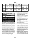
TABLE 12
Manifold and Supply Pressure (Outlet) inches w.c.
Fuel
Model
Input Sizes
Manifold
Pressure in.wg.
Supply
Pressure in.wg.
Min. Max.
Nat. Gas All sizes
3.5
4.5 10.0
L.P. Gas All sizes
10.0
11.0 13.0
NOTE − A natural to L.P. propane gas changeover kit is nec-
essary to convert this unit. Refer to the changeover kit
installation instruction for the conversion procedure.
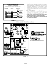
Manifold Pressure Measurement
1 − Remove the threaded plug from the outlet side of the
gas valve and install a field−provided barbed fitting.
Connect to a manometer to measure manifold pres-
sure.
2 − Start unit and allow 5 minutes for unit to reach steady
state.
3 − While waiting for the unit to stabilize, notice the flame.
Flame should be stable and should not lift from burner.
Natural gas should burn blue.
4 − After allowing unit to stabilize for 5 minutes, record
manifold pressure and compare to value given in table
12.
NOTE − Shut unit off and remove manometer as soon as an
accurate reading has been obtained. Take care to remove
barbed fitting and replace threaded plug.
Proper Combustion
Furnace should operate minimum 15 minutes with correct
manifold pressure and gas flow rate before checking com-
bustion. Take combustion sample beyond the flue outlet
and compare to the tables below. The maximum carbon
monoxide reading should not exceed 50 ppm.
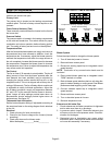
TABLE 13
ML193
Unit
CO
2
%
For
Nat
CO
2
%
For
L.P.
−045
7.2 − 7.9 8.6 − 9.3
−070
−090
−110
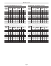
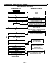
High Altitude Information
NOTE − In Canada, certification for installations at eleva-
tions over 4500 feet (1372 m) is the jurisdiction of local au-
thorities.
ML193DF units require no manifold pressure adjustments
for operation at altitudes up to 10,000 feet (3048 m) above
sea level. Units installed at altitude of 4501 − 10,000 feet
(1373 to 3048m) require a pressure switch change which
can be ordered separately. Table 14 lists conversion kit and
pressure switch requirements at varying altitudes.
The combustion air pressure switch is factory−set and re-
quires no adjustment.
NOTE − A natural to LP/propane gas changeover kit is nec-
essary to convert this unit. Refer to the changeover kit
installation instruction for the conversion procedure.