


8
6 - CONNECTING SUPPLY AND RETURN PIPING
WARNING
Burn and scald hazard. Safety relief valve could
discharge steam or hot water during operation. In-
stall discharge piping per these instructions.
!
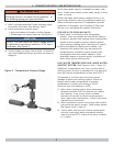
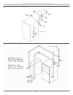
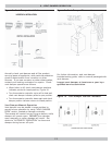
Figure 3 - Temperature Pressure Gauge
Verify clean water supply is available to water inlet
valve. Install sand strainer when water supply is from
a well or pump.
Install hot water boiler above radiation level or as
required by Authority having jurisdiction install low
water cutoff device at time of installation. Periodic
inspection is necessary, as is fl ushing of fl oat type
devices, per manufacturers specifi c instruction.
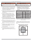
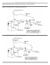
FOR USE WITH COOLING UNITS
A. Boiler used in connection with refrigeration
system, must be installed so that chilled medium
is piped in parallel with heating boiler. Appropriate
valves must be used to prevent chilled medium
from entering heating boiler. See Figure 5 page 9.
B. Boiler connected to heating coils located in air
handling units where they may be exposed to
refrigerated air circulation, piping system shall
be equipped with fl ow control valves or other
automatic means to prevent gravity circulation of
boiler water during cooling cycle.
LOW WATER TEMPERATURE AND LARGE WATER
CONTENT SYSTEM (See Figures 6 and 7, Page 10.)
Signifi cant condensation may form in boiler and/or
venting system if boiler is operated for long period of
time with return temperatures of less than 120° F.
Condensate is corrosive and can cause severe
damage to boiler and venting system. Minimum
design return water temperature to prevent
condensation in boiler and venting is 120°F.
Minimum high limit setting is 140°F.
1.
Boiler used in heating system where design water
temperatures below 140°F are desired (e.g. radiant
fl oor heating), 4-way mixing valve or suitable
alternative is required to prevent low temperature
return water from entering boiler. Follow mixing valve
manufacturer’s instructions.
2.
Boiler connected to system having large water content
(such as former gravity system), install system bypass.
See Figures 6 and 7, page 10.
3.
If boiler water reset control is used to operate boiler,
minimum reset supply water temperature setpoint
must be at least 140°F, unless mixing valve is used as
in (1) above.
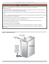
1.
Boiler is shipped assembled. Install discharge piping
from safety relief valve. See Warning, Page 7.
2.
Install temperature pressure gauge.
• Apply pipe sealant to threads on shaft of gauge.
• Thread gauge into supply water tee. See Figure 3.
NOTICE
DO NOT TIGHTEN GAUGE BY HAND!! Gauge should
be tightened using crescent wrench or 9/16” open
end wrench. See Figure 3.
3.
Connect supply and return lines to boiler. Connections
may require additional fi ttings and parts, as shown on
diagrams.