


28
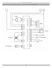
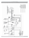
APPENDIX A - CONTROL MODULE
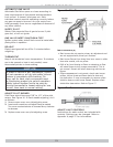
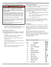
A.5 Operation
Module continuously monitors boiler water temperature and
fi res or shuts off burner based on this temperature data.
1.
When “Call for Heat” occurs, control enables circulator
and monitors boiler water temperature to determine
whether thermostat can be satisfi ed without fi ring
burners.
2.
Control determines burner operation is required,
module proceeds to start burner (see state codes list)
and heats water in boiler until setpoint temperature is
achieved or thermostat is satisfi ed. .
3.
Burner is de-activated, ignition module completes heat-
ing cycle, returns to idle and waits for temperature to
drop again.
4.
Circulator is turned on throughout “Call for Heat.”
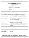
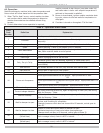
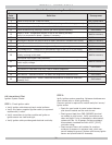
Table 6 - Operation State Codes
State
Code
Number
Defi nition Explanation
1
Idle Standby - no call for heat
Circulator
Heat request present. Boiler temperature suffi ciently high to run circulator
pump only.
4 Pre-purge System is purging before ignition trial; includes Pilot Valve circuit diagnostics.
6 Spark System sparking. Flame is not present up to 13 seconds
7 Flame stabilization
Flame signal is being established. Variation in signal is allowed during this
state, fl ame must be stable at end of period
8 Running System is running. Flame signal must be present.
9 Post-Purge System is purging at end of call for heat
10
Retry Recycle Delay
Successful ignition was not detected, and delay is called before retry.
Flame signal was lost during state 7 or 8, and delay is called before retry (32
second delay)
13 Soft lock-out Soft lockout duration is one hour, may override with manual reset.
14 Hard lock-out Manual reset is required for hard lockout
15 Wait for limit to close Possible thermostat call for heat; limit switch is open.
16 Flame out of sequence
Flame signal sensed before trial for ignition. Appropriate alarm is sent.
OR
Flame signal sensed out of sequence during post purge. Appropriate alarm is s
ent. OR
Flame signal present when not expected. Appropriate alarm is sent.
17
Pilot valve diagnostics Pilot valve circuitry diagnostics during pre-purge.
Current leakage detection
Self check performed at start up, again at beginning of heat cycle, and during
“Wait for Recovery “ State.
Wait for recovery
Self check performed at start up, again at beginning of heat cycle, and during
“Wait for Recovery “ State
18 Wait for damper to open
Control has signaled damper/pressure switch
to close, and is waiting for completion.
If damper/pressure switch does not close within 60 seconds, control goes to
State 20.
19 Wait for damper to close
Damper is closed and control waits for damper to open.
Checked at beginning of heat cycle before opening damper.
If damper does not open in 60 seconds, control goes to State 21.
20
Wait for damper to open
(Failed close)
Damper has not opened (end swich not closed) at beginning of heat cycle.
Alarm message is sent, control is NOT in lockout.
21
Wait for damper to close
(Failed open)
Damper has not closed despite actuator de-energized.
Alarm message is sent, control is NOT in lockout.