


5
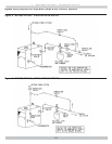
4 - INSTALLATION PROCEDURE
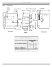
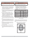
Table 3 -
MINIMUM CLEARANCE DIMENSIONS
Inches (mm)
Top 6” (152mm)
Rear 6” (152mm)
Control Side 7” (178mm)
Opposite Side 6” (152mm)
Front
18” (457mm)
Flue/Vent Connector 6” (152mm)
Near Boiler Piping 1/2” (13mm)
WARNING
Improper installation, adjustment, alteration, service
or maintenance could result in death or serious
injury
.
!
WARNING
Fire hazard. Do not install boiler on combustible
fl ooring or carpeting. Failure to follow these
instructions could result in death or serious injury.
!
1.
FOR INSTALLATION ON NON-COMBUSTIBLE
FLOORS ONLY - For installation on combustible
fl ooring special base must be used. (See Replacement
Parts Section.) Boiler can not be installed on
carpeting.
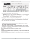
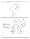
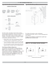
NOTE: Greater clearances for access should supersede fire
protection clearances.
* Defi nition of Alcove is three sided space with no wall in
front of boiler. ANSI standard for alcove is 18 inches from
front of appliance to leading edge of side walls as shown
below.
1.
Installation must conform to the requirements of the
authority having jurisdiction or, in the absence of such
requirements, to the National Fuel Gas Code, ANSI
Z223.1/NFPA 54, and/or Natural Gas and Propane
Installation Code, CAN/CSA B149.1.
2.
Where required by the authority having jurisdiction, the
installation must conform to the Standard for Controls
and Safety Devices for Automatically fi red Boilers,
ANSI/ASME CSD-1.
3.
Boiler series is classifi ed as a Category I. Vent
installation shall be in accordance with "Venting of
Equipment ," of the National Fuel Gas Code, ANSI
Z223.1/NFPA 54, or "Venting Systems and Air Supply
for Appliances," of the Natural Gas and Propane
Installation Code, CAN/CSA B149.1, or applicable
provisions of the local building codes.
4.
Boiler has met safe lighting and other performance
criteria with the gas manifold and control assembly on
the boiler per the latest revision of ANSI Z21.13/CGA
4.9.
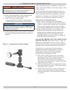
5.
Install boiler such that gas ignition system components
are protected from water (dripping, spraying, rain,
etc.) during appliance operation and service, (circulator
replacement, condensate trap, control replacement,
etc.).
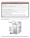
6.
Locate boiler on level, solid base as near chimney as
possible and centrally located with respect to heat
distribution system as practical.
7.
Allow 24 inches (610mm ) at front and right side for
servicing and cleaning.
8.
When installed in utility room, door should be wide
enough to allow largest boiler part to enter, or to
permit replacement of another appliance such as water
heater.
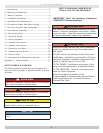
Minimum Clearances to Combustible
Construction (as seen from above)
6"
BOILER
18"
6"
Front
7"
Control
Side