


11
Boilers connecting to gas vents or chimneys, vent
installations shall be in accordance with “Venting of
Equipment”, of the National Fuel Gas Code, ANSI
Z223.1/NFPA 54 or “Venting Systems and Air Supply
for Appliances,” of the Natural Gas and Propane
Installation Code, CAN/CSA B149.1, or applicable
provisions of the local building codes.
Check Your Chimney
It must be clean, right size, properly constructed and
in good condition.
Chimney Sizing
Chimney sizing, and vent installation must be in
accordance with The National Fuel Gas Code, ANSI
Z223.1/NFPA 54 or CAN/CSA B149.1, or applicable
provisions of local building codes.
This is a high effi ciency boiler with low stack
temperature. Following recommendations are in
addition to requirements of the National Fuel Gas
Code.
1. Type B double wall vent pipe is recommended for
vent connector. Single wall vent connectors should
not be used unless following conditions are true:
a) Except for basement, boiler is not installed in
unheated space.
b) Total horizontal portion of vent connector, not
including elbows is less than 5 feet in length.
2. Outside chimneys (i.e. chimneys exposed to
outdoors below roof line) should not be used unless
they are:
a) enclosed in a chase, or
b) lined with type B vent pipe, or listed fl exible
vent liner, or other certifi ed chimney lining system.
3. Where possible it is recommended to common vent
boiler and water heater.
4. For multiple boiler installations, consult boiler
manufacturer for venting recommendations.
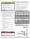
Connecting The Vent Damper And Vent
Connector
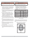
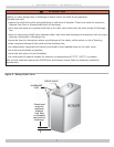
Refer to Figure 1, page 2 for size and location of vent
(fl ue opening).
NOTICE
Damper blade on furnished vent damper has 1/2
square inch hole (approximately 3/4” diameter).
Boilers equipped with intermittent ignition, hole
should be plugged by using plug supplied with vent
damper.
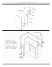
1.
Position furnished vent damper on top of fl ue outlet
collar. Fasten damper securely to fl ue outlet collar with
sheet metal screws. Verify damper blade has clearance
to operate inside of diverter. Do not modify either draft
diverter or vent damper during installation.
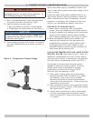
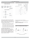
As An Option
Damper may be installed in horizontal or vertical
position, closer to fl ue outlet collar preferred. See
Figures 8, 9 and 10 and enclosed vent damper
instructions.
2.
Install vent damper to service only single boiler for
which it is intended. Damper position indicator shall be
in visible location following installation. Locate damper
so it is accessible for servicing. See Figure 9.
3.
Damper must be in the open position when appliance
main burners are operating.
4.
Boiler is equipped with factory wired harness that plugs
into vent damper.
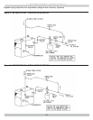
5.
Slope pipe up from boiler to chimney not less than 1/4”
per foot.
6.
Run pipe as directly as possible with as few elbows as
possible.
7.
Do not connect to fi replace fl ue.
8.
End of vent pipe must be fl ush with inside face of
chimney fl ue. Use a sealed-in thimble for chimney
connection.
Fasten sections of vent pipe with sheet metal screws
to make piping rigid. Support horizontal potions of
vent system to prevent sagging. Use stovepipe wires
every 5’ to support pipe from above. Use double wall
vent pipe if vent pipe must go through crawl space.
Where vent pipe passes through combustible wall
or partition, use ventilated metal thimble. Thimble
should be 4 inches larger in diameter than vent pipe.
7 - CHIMNEY AND VENT PIPE CONNECTION
WARNING
Boiler and venting installations shall be performed
by a qualifi ed expert and in accordance with the
appropriate manual. Installing or venting boiler
or other gas appliance with improper methods or
materials may result in serious injury or death due
to fi re or to asphyxiation from poisonous gases such
as carbon monoxide with is odorless and invisible.
!