


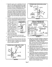

The following repair parts are available through independent Lennox dealers. When ordering parts, include the complete
furnace model number listed on the unit rating plate. Example: G32Q3-75-1.
CABINET PARTS
Cabinet cap
Blower panel
Upper access panel
CONTROL PANEL PARTS
Two-Stage control board
Surelight TM integrated control board
Transformer
Circuit breaker
Door interlock switch
BLOWER PARTS
Blower wheel
Motor
Motor mounting frame (Q4/5 only)
Motor capacitor
Blower housing cut-off plate
Blower housing
HEATING PARTS
Heat exchanger/coil assembly
Gas manifold
Combustion air inducer
Main burner orifices
Main burners
Two-stage gas valve
Ignitor
Primary limit control
Flame rollout switch
Filter and filter rack assembly
Flue transition
Pressure switch - high heat (-75 only)
Pressure switch - low heat
Flame sensor
Sight glass and grommet
Rubber boot trap
Foam manifold gaskets
Two-speed combustion air inducer
Condensate pipe plug and adapter
Cold end header (collector) box
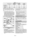
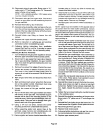
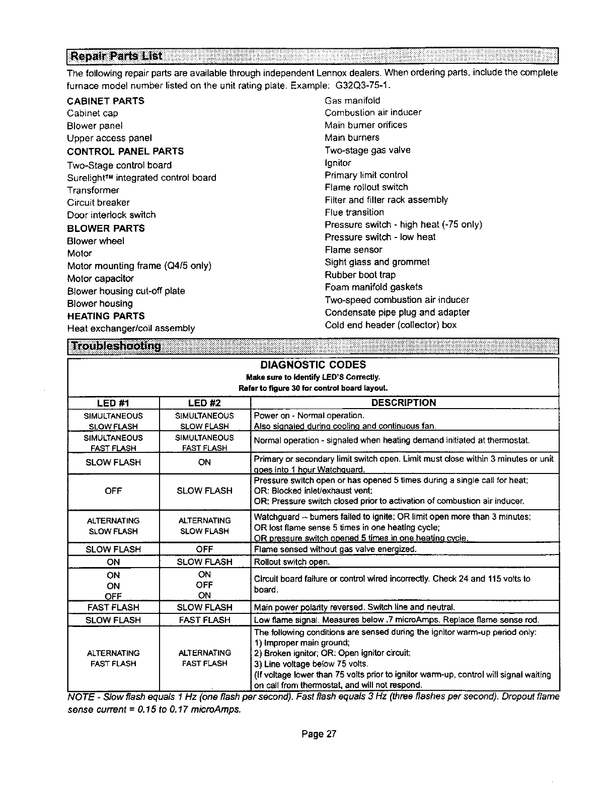
Make sure to Identify LED'S Correctly.
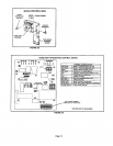
Refer to figure 30 for control board layout.
LED #1
SIMULTANEOUS
SLOW FLASH
SIMULTANEOUS
FAST FLASH
SLOW FLASH
OFF
ALTERNATING
SLOW FLASH
LED #2
SIMULTANEOUS
SLOWFLASH
SIMULTANEOUS
FASTFLASH
ON
SLOW FLASH
ALTERNATING
SLOW FLASH
DESCRIPTION
Power on - Normaloperation.
Also siqnaleddudnq coolin,qand continuousfan
Normal operation- signaledwhen heating demand initiatedat thermostat.
Primary or secondarylimit switch open. Limitmust close within 3 minutes or unit
qqes into 1 hour Watchouard,
Pressure switchopen or has opened 5 times during a single carl for heat;
OR: Blocked inlet/exhaust vent;
OR: Pressure switchclosed prior to activationof combustion air inducer.
Watchguard - burners failedto ignite;OR limit open more than 3 minutes;
OR lost flame sense 5 times inone heating cycle;
OR pressure switchopened 5 times inone heatino cvcle.
Flame sensedwithoutgas valve energized.
SLOW FLASH OFF
ON SLOW FLASH Rollout switchopen.
ON ON Cimuitboard failure or controlwired incorrectly.Check 24 and 115 voltsto
ON OFF board.
OFF ON
FAST FLASH SLOW FLASH Main power polarity reversed. Switchline and neutral.
SLOW FLASH FAST FLASH Low flame signal. Measures below.7 micmAmps. Replace flame sense rod.
The followingconditionsare sensed duringthe ignitorwarm-up period only:
1) Improper mainground;
ALTERNATING ALTERNATING 2) Brokenignitor;OR: Open ignitorcircuit;
FASTFLASH FASTFLASH 3) Linevoltage be{ow 75 volts.
(If voltage towerthan 75 volts pdor to ignitor warm-up, control will signalwaiting
on call from thermostat, and will not respond.
NOTE - Slow flash equals 1 Hz (one flash per second). Fast flash equals 3 Hz (three flashes per second). Dropout flame
sense current = 0.15 to 0.17 microAmps.
Page 27