


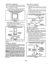
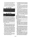

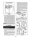
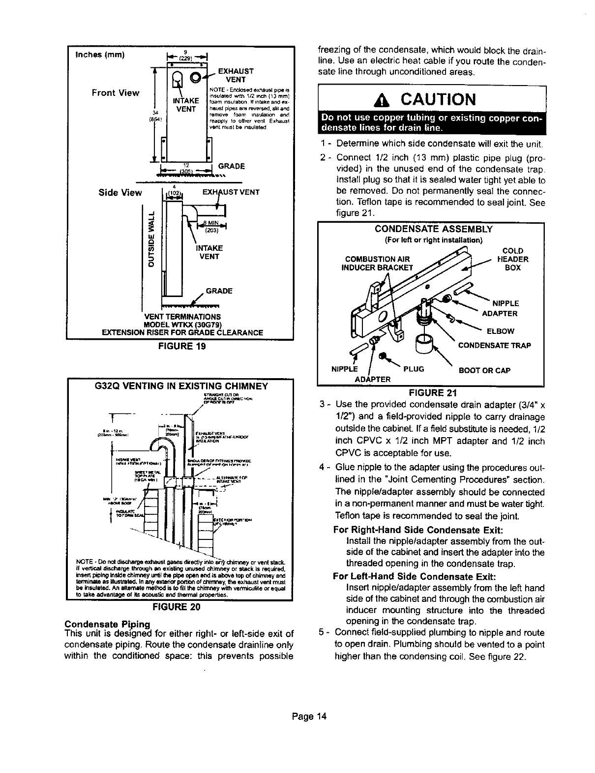
Inches (mm)
Front View
[
34
9
_,EXHAUST
I '10" VENT
= _ NOTE -Enclosed ex_us_ pipe _s
insuleted w;th _F2 i,_Ch(13 ram)
INTAKE foam insu_abon If in_al(ear_ ex-
VENT hsusl I_pes am reversed, sl=land
r_move foam instJlat_ot_ and
Ii teat)ply to OUmr vent Exhaust
vent mr=st be insulated
Side View
4
USTVENT
o
iNTAKE
VENT
E
VENT TERMINATIONS
MODEL WTKX (30GT9)
EXTENSION RISER FOR GRADE CLEARANCE
FIGURE 19
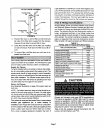
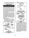
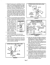
G32Q VENTING IN EXISTING CHIMNEY
NOTE -Do not dischal_e exhaust gases ditently into or vent stack.
II ventCal discharge through at, ex_6ng unused chimney or stack ts require<J,
i_sertpipingintgde chlm,'.eyurdilthe pipeopenendIsabovetopof _y and
termimlte as iltusttstad. I. any extedor po(tlon of ¢ilrmney, the exhaust vent must
be insulated.An alternatemethodistoflitthechimneywithvetrmc.ulitoorequal
to take advantage of its acoustic and thermal properties,
FIGURE 20
Condensate Piping
This unit is designed for either right- or left-side exit of
condensate piping. Route the condensate drainiine only
within the conditioned space: this prevents possible
freezing of the condensate, which would block the drain-
line. Use an electric heat cable if you route the conden-
sate line through unconditioned areas.
A CAUTION
1 - Determine which side condensate will exit the unit.
2- Connect 1/2 inch (13 mm) plastic pipe plug (pro-
vided) in the unused end of the condensate trap.
Install plug so that it is sealed water tight yet able to
be removed. Do not permanently seal the connec-
tion. Teflon tape is recommended to seal joint. See
figure 21.
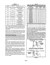
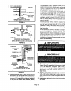
CONDENSATE ASSEMBLY
(Forleftor rightinstallation)
COLD
COMBUSTION AIR HEADER
INDUCER BRACKET BOX
ADAPTER
ELBOW
CONDENSATE TRAP
NIPPLE BOOTORCAP
ADAPTER
FIGURE 2t
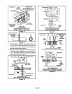
3 - Use the providedcondensate drain adapter (3/4" x
1/2") and a field-providednipple to carry drainage
outside the cabinet. If a fieldsubstitute is needed, 1/2
inch CPVC x 1/2 inch MPT adapter and 1/2 inch
CPVC is acceptable for use.
4 - Glue nipple to the adapter using the procedures out-
lined in the "Joint Cementing Procedures" section.
The nipple/adapter assembly should be connected
in a non-permanentmanner and must be water tight.
Teflon tape is recommended to seal the joint.
For Right-Hand Side Condensate Exit:
Install the nipple/adapter assembly from the out-
side of the cabinet and insert the adapter intothe
threaded opening in the condensate trap.
For Left-Hand Side Condensate Exit:
Insert nipple/adapterassemblyfrom the left hand
side of the cabinet and through the combustion air
inducer mounting structure into the threaded
opening in the condensate trap.
5 - Connect field-supplied plumbing to nipple and route
to open drain. Plumbing should be vented to a point
higher than the condensing coil. See figure 22.
Page14