


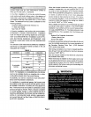
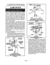
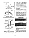
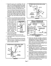
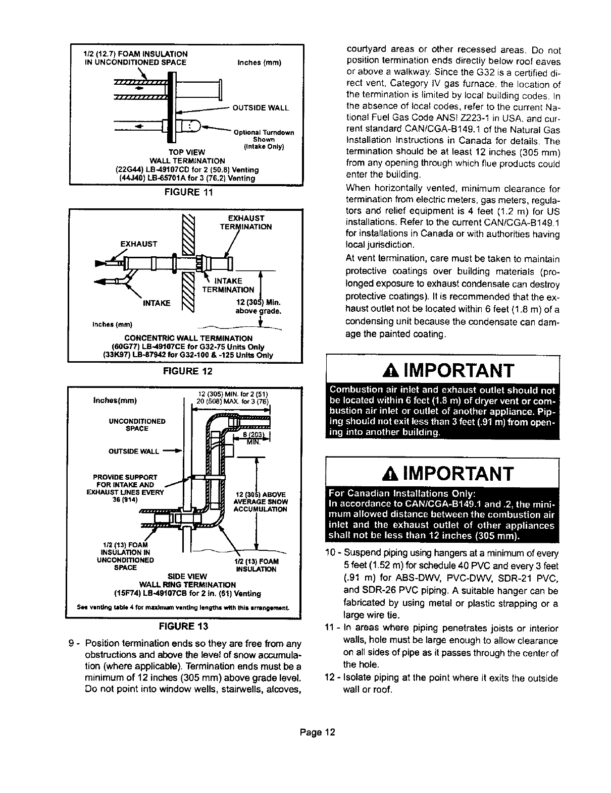
1/2 (12.7) FOAM INSULATION
IN UNCONDITIONED SPACE
Inches (mm)
n
OUTSIDEWALL
qlp
Optional Turndown
Shown
(Intake Onty)
TOPVIEW
WALLTERMINATION
(22G44)LB-49107CDfor2 (50,8)Venting
(44J40)LB-65701Afor3 (76.2)Venting
FIGURE 11
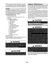
EXHAUST
INTAKE
Inches (ram)
EXHAUST
TERMINATION
abovegrade,
CONCENTRIC WALL TERMINATION
(60G77) LB-49107CE for G32-75 Units Only
(331(97) LB-87942 for G32-t00 & -125 Units Only
FIGURE 12
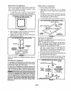
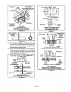
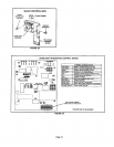
Inches(mm)
UNCONDITIONED
SPACE
OUTSIDE WALL
PROVIDE SUPPORT
FOR INTAKE AND /
EXHAUST UNES EVERY
3_(914)
1/2113) FOAM
INSULATION IN
UNCONOmONED
SPACE
12 (305) MIN for2 (51)
20(5oa)MAXfor3(76):
F
HI II t2(S_0)ASOVE
Ii2 (131FOAM
INSULATION
SiDEVIEW
WALLRINGTERMINATION
(15F74)LE-49107CBfor2 In. (51)Venting
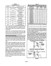
See v.ntlng table 4 for maglng_ venting lengths with this Irmr:l_mant.
FIGURE 13
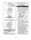
9 - Position terminationends so they are free from any
obstructions and abovethe level of snowaccumula-
tion (where applicable). Termination ends must be a
minimum of 12 inches (305 mm) above grade level.
Do not point into window wells, stairwells, alcoves,
courtyard areas or other recessed areas. Do not
position termination ends directly below roof eaves
or above a walkway. Since the G32 is a certified di-
rect vent, Category iV gas furnace, the location of
the termination is limited by local building codes. In
the absence of local codes, refer to the current Na-
tional Fuel Gas Code ANSI Z223-1 in USA, and cur-
rent standard CAN/CGA-B149.1 of the Natural Gas
Installation Instructions in Canada for details. The
termination should be at least 12 inches (305 mm)
from any opening through which flue products could
enter the building.
When horizontally vented, minimum clearance for
termination from electric meters, gas meters, regula-
tors and relief equipment is 4 feet (1.2 m) for US
installations. Refer to the current CAN/CGA-B149.1
for installations in Canada or with authorities having
local jurisdiction.
At vent termination, care must be taken to maintain
protective coatings over building materials (pro-
longed exposure to exhaust condensate can destroy
protective coatings). It is recommended that the ex-
haust outlet not be located within 6 feet (1.8 m) of a
condensing unit because the condensate can dam-
age the painted coating.
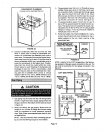
10 - Suspend piping using hangers at a minimum ofevery
5 feet (1.52 m) for schedule 40 PVC and every 3 feet
(.91 m) for ABS-DWV, PVC-DWV, SDR-21 PVC,
and SDR-26 PVC piping. A suitable hanger can be
fabricated by using metal or plastic strapping or a
large wire tie.
11 - In areas where piping penetrates joists or interior
walls, hole must be large enough to allow clearance
on all sides of pipe as it passes through the center of
the hole.
12 - Isolate piping at the point where it exits the outside
wall or roof.
Page 12