


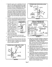
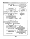

34 - Reconnect widng to gas valve. Brown wire to "HI,"
yellow wire to "C" and orange wire to "M." Reconnect
wires to name roll-out switch.
NOTE - Unit is polarity-sensitive. 120V supply wiring
must be installed correctly
35 - Reconnect main gas line to gas valve. Use second
wrench on gas valve to avoid transferring torque to
the gas manifold.
36 - Reinstall field make-up box if removed.
37 - Reinstall exhaust pipe/flue collar and secure flue col-
lar to the unit top cap using existing screw. Insert the
bottom of the flue collar into the top of the flue transi-
tion and tighten hose clamp.
38-Reinstall intake pipe fitting on burner box with
screws.
39 - Replace both upper and lower access panels.
40 - Refer to instruction on verifying gas and electrical
connections when re-establishing supply.
41-Following lighting instructions from installation
manual, light and run unit for 5 minutes to ensure
heat exchanger is clean, dry and operating safely.
Cleaning the Bumer Assembly
1 - Turn off electrical and gas power supplies to furnace.
Remove upper and lower furnace access panels.
2 - Disconnect the gas supply line to gas valve. Depend-
ing on gas plumbing installation, the gas manifold
may move aside enough that breaking the union may
not be necessary.
3 - Remove five screws from edges of burner box cover.
4 - Loosen two screws on bottom of burner box front.
The cover is key holed at these screw point so
screws do not need to be removed. Pull off cover and
set aside.
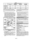
6 - Mark all gas valve wiresand disconnect them from
valve.
7 - Mark and disconnect sensor wires from the burner
box at the ignition control. Disconnect 2-pin plug
from the ignitor at the burner box.
8- Loosen two screws at the gas manifold support
bracket.
9 - Pull on the left side of the gas manifold and follow
with tension to the right side. The manifold support
bracket will be free of the mounting screwson the
vestibule panel. Set the gas manifold/gas valve as-
sembly aside. Take care not to damage foam gas-
kets on each end of the gas manifold.
10-Using a 1/4 inch nut driver, remove the burner
mountingscrews from underneaththe burners.
11-While supporting ignitor and sensor lines at the
grommet, grasp burners and simultaneously pull
burners and grommet out of the burner box.
12 - Remove ignitor and sensor bracket assemblies from
burners using a 1/4 inch nut driver to remove two
screws from each bracket.
13 - Clean burner by running a vacuum with a soft brush
attachment over face of burners. Use burner brush
to clean inside of burners. Visually inspect inside of
burners and crossovers for any blockage caused by
foreign matter. Remove any blockage.
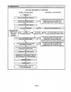
14 - Reinstall ignitor and sensor bracket assemblies on
burners.
NOTE - Ignitor must be installed on the opposite side of
the burner from the metal button protrusions. Screws
which attached the ignitor bracket must be installed from
the same side as theignitor and through the bracket toen-
gage in the smaller holes located in the burner. The cor-
rect burner orientation is with metal button protrusions al-
ways pointing up.
15 - Replace burner ignitor assembly back into burner
box so that grommet groove fits back intosheet met-
al notch and makes a good seal. The bumers sit on
top of the burner box flanges. Make certain that the
screws from underneath the box pass through the
larger holes in the flange and engage in the smaller
holes in the burner. Reinstall the two screws.
16 - Reinstall the gas manifold/gas valve assembly by
first inserting the right hand side of the gas manifold
into the burner box. Swing left side of manifold into
box while engaging support bracket to vestibule pan-
el screws. Check that foam gaskets are providing a
seal around each end ofthe gas manifold.All gas ori-
rices should be engaged. If at this point the burners
were mounted in the wrong holes, this needs to be
corrected. The saddle brackets on the gas manifold
should be flush with the front surfaces on the burner
box sides.
17 - inspect the dual layered metal piecesat thefront lip
of the cover. These pieces must sandwich around
the metal. Reinstall burner box cover.
18 - Reinstallthe screws to secure the burner box cover.
Make sure screws are tight to ensure a leak tight
burner box. Tighten the two screws underneath the
box. Again, inspect the grommet to ensure a tight
seal.
19 - -tighten the two screws holding the manifold bracket
to the vestibule panel.
20 - Reinstallthe electricalconnections to the gas valve.
Brown wire to "HI" yellow wire to "C"and orange wire
to "M."
21 - Reinstall the 2-pin ignitor plug at the burner box. Re-
install sensor line to ignition control spade connector.
22 - Reconnect gas line to gas valve.
23 - Replace lower access panel.
24 - Following lighting instructions and gas line connec-
tion test procedures from installation manual.
25 - Replace upper access panel.
Page 26