


506470-01 Issue 1007
4. Remover the existing R-22 refrigerant flow control orifice
or thermal expansion valve before continuing with flushing
procedures. R-22 flow control devices are not approved for
use with R410A refrigerant and may prevent proper flushing.
Use a field-provided fitting to reconnect the lines.
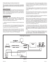
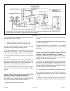
5. Remove the pressure tap valve cores from the 4HP18LT
units service valves. Connect an R-22 cylinder with clean
refrigerant to the suction service valve. Connect the R-22
gauge set to the liquid line valve and connect a recovery
maching with an empty recovery tank to the gauge set.
6. Set the recovery machine for liquid recovery and start
the recovery machine. Open the gauge set valves to allow
the recovery machine to pull a vacuum on the existing system
line set and indoor coil.
7. Invert the cylinder of clean R-22 and open its valve to
allow liquid refrigerant to flow in to the system through the
suction line valve. Allow the refrigerant to pass from the
cylinder and through the line set and the indoor coil before it
enters the recovery machine.
8. After all of the liquid refrigerant has been recovered, switch
the recovery machine to vapor recovery so that all of the R-
22 vapor is recovered. Allow the recovery machine to pull a
vacuum on the sytem.
NOTE: A single system flush should remove all of the mineral
oil from the existing refrigerant lines and indoor coil. A second
flushing may be done (using clean refrigerant) if insufficient
amounts of mineral oil were removed during the first flush.
After each system flush, allow the recovery machine to
pull a vacuum on the system at the end of the procedure.
9. Close the valve on the inverted R-22 cylinder and the
gauge set valves. Pump the remaining refrigerant out of
the recovery machine and turn the machine off.
10. Use nitrogen to break the vacuum on the refrigerant
lines and indoor coil before removing the recovery machine,
gauges, and R-22 refrigerant drum. Re-install pressure tap
valve cores into the 4SHP18LT unit’s service valves.
11. Install the fixed orifice (or thermal expansion valve
approved for use with R410A refrigerant) in the liquid line at
the indoor coil.
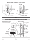
Refrigerant Metering Device
4HP18LT units are designed for use with TXV systems.
Refer to the appropriate following section for information on
installing the chosen refrigerant metering device.
An R410A system will not operate properly with an R-22
metering device.
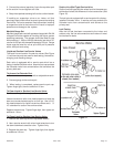
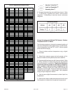
Install the refrigerant metering device as shown in Figure
11. Do not twist cap tubes when loosening the seal nut from
the orifice housing. Use wrench to back up the distributor.
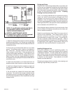
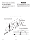
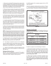
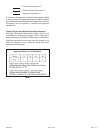
Expansion Valve Systems
Expansion valves equipped with Chatleff-type fittings are
available from the manufacturer. See Table 3 for proper
TXV for each unit.
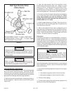
To install an expansion valve (See Figure 10 above):
1. Separate the distributor assembly and remove the piston
orifice and used teflon seal. Insert nozzle end of the
expansion valve along with a new teflon seal into the
distributor and tighten to 20 - 30 ft. lbs. Use backup wrench
on all wrench flats. Overtightening will crush the teflon
seal and may cause a leak.
2. Attach liquid line portion of distributor assembly along
with new teflon seal to the inlet of the expansion valve.
Tighten to 20 - 30 ft. lbs. Use backup wrench on all wrench
flats. Overtightening will crush the teflon seal and may
cause a leak.
Page 9
Figure 10
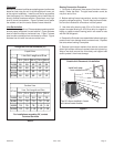
Table 3
MODEL PART NUMBER
4HP18LT- 24
4HP18LT - 36
H4TXV01
H4TXV02
4HP18LT - 48, -60 H4TXV03
TXV Data