


506470-01 Issue 1007
INSTALLATION
Inspection of Shipment
Upon receipt of equipment, carefully inspect it for possible
shipping damage. If damage is found, it should be noted on
the carrier’s freight bill. Take special care to examine the
unit inside the carton if the carton is damaged. Any concealed
damage discovered should be reported to the last carrier
immediately, preferably in writing, and should include a
request for inspection by the carrier’s agent.
If any damages are discovered and reported to the carrier
DO NOT INSTALL THE UNIT, as claim may be denied.
Check the unit rating plate to confirm specifications are
as ordered.
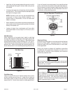
Location of Unit
Outdoor units operate under a wide range of weather
conditions; therefore, multiple factors must be considered
when positioning the unit. The unit must be positioned to
give adequate clearances for sufficient airflow and servicing.
Refer to Figure 1 for installation clearances.
General
Read this entire instruction manual, as well as the
instructions supplied in separate equipment, before
starting the installation. Observe and follow all
warnings, cautions, instructional labels, and tags.
Failure to comply with these instructions could result
in an unsafe condition and/or premature component
failure.
These instructions are intended as a general guide only for
use by qualified personnel and do not supersede any national
or local codes in any way. The installation must comply with
all provincial, state, and local codes as well as the National
Electrical Code (U.S.) or Canadian Electrical Code (Canada).
Compliance should be determined prior to installation.
4HP18LT condensing units use R410A which is an ozone-
friendly HFC refrigerant. The unit must be installed with a
matching indoor coil and line set. A filter drier approved for
use with R410A is installed in the unit.
IMPORTANT: This product has been designed and
manufactured to meet ENERGY STAR criteria for energy
efficiency when matched with appropriate coil components.
However, proper refrigerant charge and proper air flow are
critical to achieve rated capacity and efficiency. Installation
of this product should follow the manufacturer’s refrigerant
charging and air flow instructions. Failure to confirm proper
charge and airflow may reduce energy efficiency and
shorten equipment life.
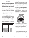
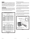
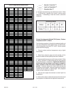
When servicing or repairing HVAC components, ensure the
fasteners are appropriately tightened. Table 1 shows torque
values for fasteners.
• Place a sound-absorbing material, such as Isomode
under the unit if it will be installed in a location or position
that will transmit sound or vibration to the living area or
adjacent buildings..
Page 2
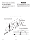
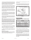
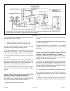
Figure 1
Installation Clearances
* A service clearance of 30" must be maintained on
one of the sides adjacent to the control box.
Clearance to one of the other three sides must be
36". Clearance to one of the remaining two sides may
be 12" and the final side may be 6".
A clearance of 24" must be maintained between units.
48" clearance required on top of unit. Maximum soffit
overhang is 36".
36” *
36” *
36”
36”
Table 1
Torque Table
Compressor Bolts
90 in. lbs.
#10 Machine Screws
28 in. lbs.
#8 Machine Screws
16 in. lbs.
Sheet Metal Screws
16 in. lbs.
Service Port Caps 8 ft. lbs.
Stem Caps 8 ft. lbs.
Fastener Torque