


506470-01 Issue 1007
OPERATION
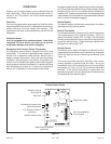
Outdoor unit and indoor blower cycle on demand from the
room thermostat. When the thermostat blower switch is
moved to the ON position, the indoor blower operates
continuously.
Filter Drier
The unit is equipped with a large capacity bi-flow filter which
keeps the system clean and dry. If replacement is necessary,
replace with one of similar design and capacity. The
replacement filter drier must be suitable for use with R410A
refrigerant.
Crankcase Heater
If unit is equipped with a crankcase heater, it should be
energized 24 hours before unit start-up to prevent
compressor damage as a result of slugging.
Emergency Heat Function (Room Thermostat)
An emergency heat function is designed into some room
thermostats. This feature is applicable when isolation of
outdoor unit is required or when auxiliary electric heat is
stage by outdoor thermostats. When the room thermostat
is placed in the emergency heat position, the outdoor unit
control circuit is isolated from power and the field-supplied
relays bypass the outdoor thermostats. An amber indicating
light simultaneously comes on to remind the homeowner
that the unit is operating in the emergency heat mode.
Emergency heat is usually used during an outdoor shutdown,
but it should also be used following a power outage if power
has been off for over an hour and the outdoor temperature
is below 50°F. System should be left in the emergency heat
mode at least 6 hours to allow the crankcase heater sufficient
time to prevent compressor slugging.
Defrost System
The defrost system includes two components: the defrost
thermostat and the defrost control.
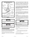
Defrost Thermostat
The defrost thermostat is located on the liquid line between
the check/expansion valve and the distributor. When the
defrost thermostat senses 42°F or cooler, the thermostat
contacts close and send a signal to the defrost control board
to start the defrost timing. It also terminates defrost when
the liquid line warms up to 70°F.
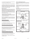
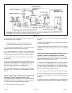
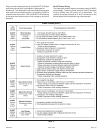
Defrost Control
The defrost control board includes the combined functions
of time/temperature defrost control, defrost relay, diagnostic
LEDS and terminal strip for field wiring connections (See
Figure 14).
The control provides automatic switching from normal
heating operation to defrost mode and back. During the
compressor cycle (call for defrost), the control accumulates
compressor run time at 30, 60, 90 minute field adjustable
intervals. If the defrost thermostat is closed when the
selected compressor run time interval ends, the defrost relay
is energized and the defrost begins.
Page 18
Figure 14
Defrost Interval
Timing Pins
Diagnostic LEDs
24V TerminalStrip
Connections
High Pressure Switch
(optional)
Defrost Thermostat
Reversing Valve
Compressor Delay Pins
Test Pins
K1 Relay
K2 Relay
FAN
DS1
L
24V
P2
P5
O-OUT
DF
Y1-OUT
HI-PS
U1
U2
DS2
K3 Relay
P6
TST PS DF C R O Y1
C5
LO-PS
C2
P1
30
60
90
TEST
W1
C
L
R
Y1
O
Low Pressure Switch
(optional)
Defrost Control Board