


506470-01 Issue 1007
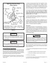
Defrost Control Timing Pins
Each timing pin selection provides a different accumulated
compressor run time period during one thermostat run cycle.
This time period must occur before a defrost cycle is initiated.
The defrost interval can be adjusted to 30 (T1), 60 (T2), or
90 (T3) minutes. The defrost timing jumper is factory
installed to provide a 60 minute defrost interval. If the timing
selector jumper is not in place, the control defaults to a 90
minute defrost interval. The maximum defrost period is 14
minutes and cannot be adjusted.
A test option is provided for troubleshooting. The test mode
may be started any time the unit is in the heating mode and
the defrost thermostat is closed or jumpered. If the jumper
is in the TEST position at power up, the control will ignore
the test pins. When the jumper is placed across the TEST
pins for 2 seconds, the control will enter the defrost mode.
If the jumper is removed before an additional 5 second period
has elapsed (7 seconds total), the unit will remain in defrost
mode until the defrost thermostat opens or 14 minutes have
passed. If the jumper is not removed until after the additional
5 second period has elapsed, the defrost will terminate and
the test option will not function again until the jumper is
removed and reapplied.
Compressor Delay
The defrost board has a field-selectable function to reduce
occasional sounds that may occur while the unit is cycling in
and out of the defrost mode. The compressor will be cycled
off for 30 seconds going in and out of the defrost mode when
the compressor delay jumper is removed.
NOTE: The 30-second “off” cycle is not functional when
jumpering the TEST pins.
Time Delay
The timed-off delay is 5 minutes long. The delay helps to
protect the compressor from short cycling in case the power
to the unit is interrupted or a pressure switch opens. The
delay is bypassed by placing the timer select jumper across
the TEST pins for 0.5 seconds.
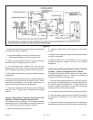
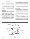
Pressure Switch Circuit
The defrost control includes two pressure switch circuits. A
high pressure switch is connected to the board’s HI-PS
terminals(See Figure 14). The low pressure, or loss-of-
charge pressure, switch is connected to the LPS terminals.
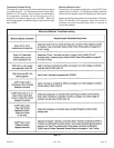
During a single demand cycle, the defrost control will lock
out the unit after the fifth time that the circuit is interrupted
by an pressure switch wired to the control board. In addition,
the diagnostic LEDs will indicate a locked-out pressure switch
after the fifth occurrence of an open pressure switch (See
Table 9). The unit will remain
locked out until power to the board is interrupted, then re-
established, or until the jumper is applied to the TEST pins
for 0.5 seconds.
NOTE: The defrost control board ignores input from the
low pressure switch terminals as follows:
• During the TEST mode
• During the defrost cycle
• During the 90 seconds start-up period
• For the first 90 seconds each time the reversing
valve switches heat/cool modes
If the TEST pins are jumpered and the 5 minute delay is
being bypassed, the LO-PS terminal signal is not
ignored during the 90-second start-up period.
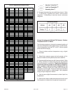
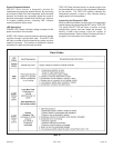
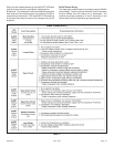
Diagnostic LEDs
The defrost board uses two LEDs for diagnostics. The LEDs
flash a specific sequence according to the condition as
shown in Table 9.
Page 19
Table 9
Defrost Control Board
Diagnostic LEDs