


14
14
INSTALLATION
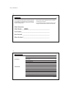
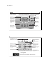
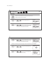
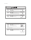
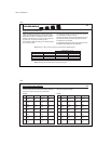
TABLE A – TERMINAL DESCRIPTIONS (continued)
TERMINAL FUNCTION FUNCTION
LABELS (HEAT PUMP MODE) (MULTI-STAGE MODE) COMMENTS
E Emergency heating DO NOT CONNECT Activates Emergency heating ONLY when the System Switch is in
Emergency (em) Mode. (Ignored on Multi-stage systems)
O Reversing valve Cooling damper Activates reversing valve or damper in COOL mode.
(cooling mode) ALWAYS ON in COOL MODE.
B Reversing valve Heating damper Activates reversing valve or damper in HEAT mode.
(heating mode) ALWAYS ON in HEAT MODE.
GFan Fan Activates the system Fan. (Can be Auto, On, or Program controlled)
L System monitor System monitor Activates System Check LED on the front of thermostat.
(Controlled by the system, not the thermostat.)
C 24VAC common 24VAC common Common wire of 24VAC transformer. REQUIRED for thermostat operation.
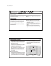
RS1+ Remote temperature Remote temperature Positive (+) Terminal for Remote Sensor #1. Polarity MUST be maintained.
sensor 1 sensor 1
RS1- Remote sensor 1 (common) Remote sensor 1 (common) Negative (-) Terminal for Remote Sensor #1. Polarity MUST be maintained.
RS2+ Remote temperature Remote temperature Positive (+) Terminal for Remote Sensor #2. Polarity MUST be maintained.
sensor 2 sensor 2
RS2- Remote sensor 2 (common) Remote sensor 2 (common) Negative (-) Terminal for Remote Sensor #2. Polarity MUST be maintained.
OPTIONAL
41653_model43558.pmd
15
15
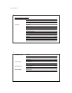
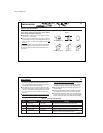
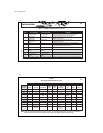
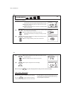
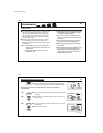
TABLE B
HEAT PUMP CROSS-REFERENCE CHART
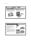
NOTE:
If your heat pump thermostat does not have an E wire, use the provided jumper wire to connect the E terminal to
the W2 terminal, as shown in three examples above. Refer to the Wiring Diagrams on pages 58-59.
EXAMPLES OF DIFFERENT SYSTEM TERMINALS
CLIMATE
TECHNOLOGY BRYANT, RHEEM- TRANE,
TERMINALS CARRIER COLEMAN COMFORTMAKER PAYNE RUUD WEATHERTRON YORK LENNOX (1) LENNOX (2)
R RR R RRRRRV-VR
Y1 Y or Y1 Y Y Y Y Y Y Y M
W2 W2 W2 W1 W2 W2 W W W1 Y
E EEjumper E E X2 jumper E E
to W2 to W2
O OOOOOOR
B BB
G GG G GGGGGF
L L or F L L or X L L X L
C CXC, X, X1 C, C1, X1 X B B C X
Note: W2 wires Note:
no connection T wire no
connection