


58
58
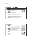
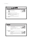
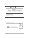
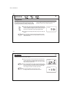
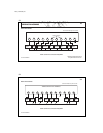
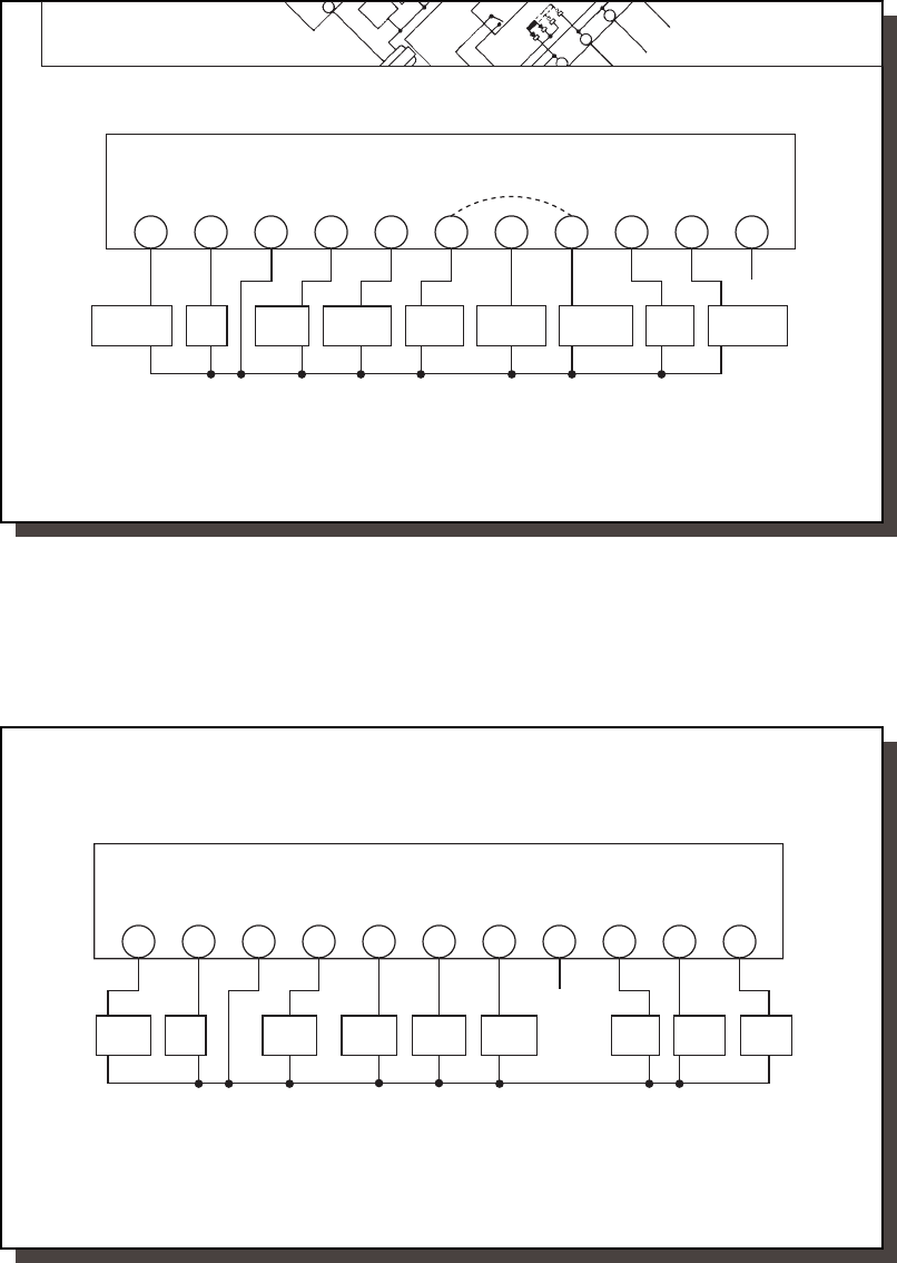
WIRING DIAGRAMS
HEAT PUMP SYSTEMS
X - No Connection
NOTE:
Common wire connection is REQUIRED.
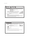
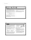
X
Optional Jumper*
THERMOSTAT WALLPLATE TERMINALS
Y2
G C L O
W2
E R
Y1
B
Fan
Relay
W1
Compressor
Stage 2
System
Monitor
Reversing
Valve Cool
Auxiliary
Heat
Emergency
Heat
24V
Supply
Compressor
Stage 1
Reversing
Valve Heat
Common
Some terminals may not be used
*Add jumper between W2 and E
on systems without an E wire.
41653_model43558.pmd
59
59
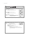
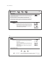
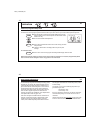
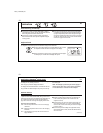
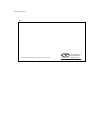
MULTI-STAGE SYSTEMS
X - No Connection
NOTE:
Common wire connection is REQUIRED.
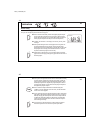
X
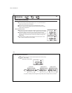
THERMOSTAT WALLPLATE TERMINALS
Y2
G C L O
W2
R
Y1
B
Fan
Relay
W1
System
Monitor
24V
Supply
Common
Some terminals may not be used
Cool
Stage 2
Cool
Damper
Heat
Stage 2
Heat
Damper
E
Heat
Stage 1
Cool
Stage 1