


10
10
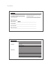
INSTALLATION
What You Need
This thermostat includes two #8 slotted screws and two wall an-
chors for mounting. To install your thermostat, you should have
the following tools and materials.
■
Slotted Screwdriver(s)
■
Electric drill and 3/16" bit
■
Phillips Screwdriver
■
Two 1.5 V (AA) size alkaline batteries
■
Hammer
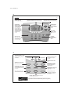
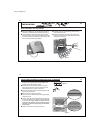
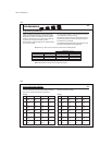
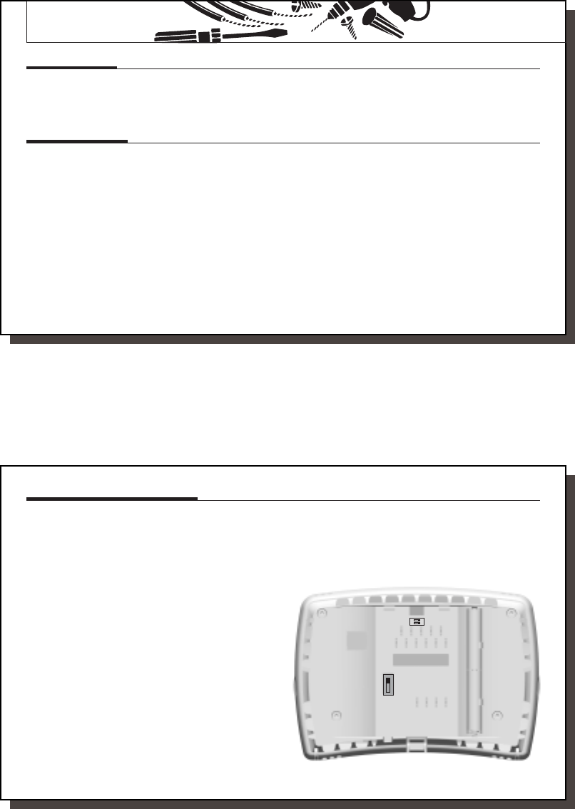
Selector Switches
In order for this Climate Technology thermostat to control your
system, the system type must be specified by selector switch
on the rear inside if the thermostat. There are also other selec-
tor switches that allow you to customize the features to suit
your needs. Refer to Figure 2 for removal of wallplate.
NOTE:
When changing these features after installation,
move the power switch to OFF before removing the ther-
mostat from the wall.
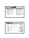
System Selector Switches:
■
Heat Pump or Multi-Stage selector (HP-MS switch)
The factory position for this switch is in the “HP” position.
Leave it in this position if you have a heat pump system or
need emergency heat control.
If you have a conventional multi-stage system (more than 1
stage of heat or cool), then slide the switch to the “MS”
position.
NOTE:
The Emergency Heat Function operates both
stages of heat at the same time when in multi-stage
mode.
41653_model43558.pmd
11
11
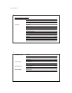
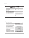
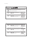
HP-HEAT PUMP
MS-MUTI-STAGE
ATTENTION: This
thermostat is powered by
24V AC from the system.
Please istall 2 AAA alkaline
batteries for clock and
memory backup.
Low Batt Warning Disable Low Batt Warning Enable
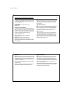
HG
HE
ON
1
2
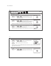
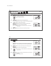
■
Heating system selector (HG - HE switch)
The factory position for this switch is in the “HG” position. Leave it
in this position if you have a gas furnace or an oil burner.
If you have an electric furnace, test to see whether the Heat
and Fan come on as expected.
If Fan operation is normal, leave the switch in the “HG” position.
If the Fan does not come on within a minute of the thermo-
stat calling for Heat, change the switch position to “HE.”
This selector has no effect in the cooling mode.
NOTE:
“HG” position is for gas and most other systems.
“HE” position is for certain electric systems having a
fan relay.
NOTE:
This option is ignored when heat pump (HP) sys-
tem is selected.
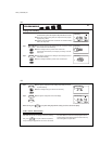
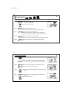
■
Low Battery Warning Selector
This Climate Technology thermostat operates on your system’s
24V AC supply. Two AAA batteries may be installed to provide
clock operation and program retention during power outages.
The factory position for this switch has the Low Battery Warn-
ing Enabled. If the thermostat is to be used without batteries,
Selector Switches (continued)
the switch can be moved to Disable. In this position, the Low
Battery Warning will not be displayed.
Climate Technology recommends that the Low Battery Warn-
ing be activated by sliding the switch to Enable, especially on
residential systems.
Figure A