


Page 28
1 − The power supply wiring must meet Class I restric-
tions. Protected by either a fuse or circuit breaker, se-
lect circuit protection and wire size according to unit
nameplate.
NOTE − Unit nameplate states maximum current draw. See
table for maximum over−current protection.
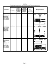
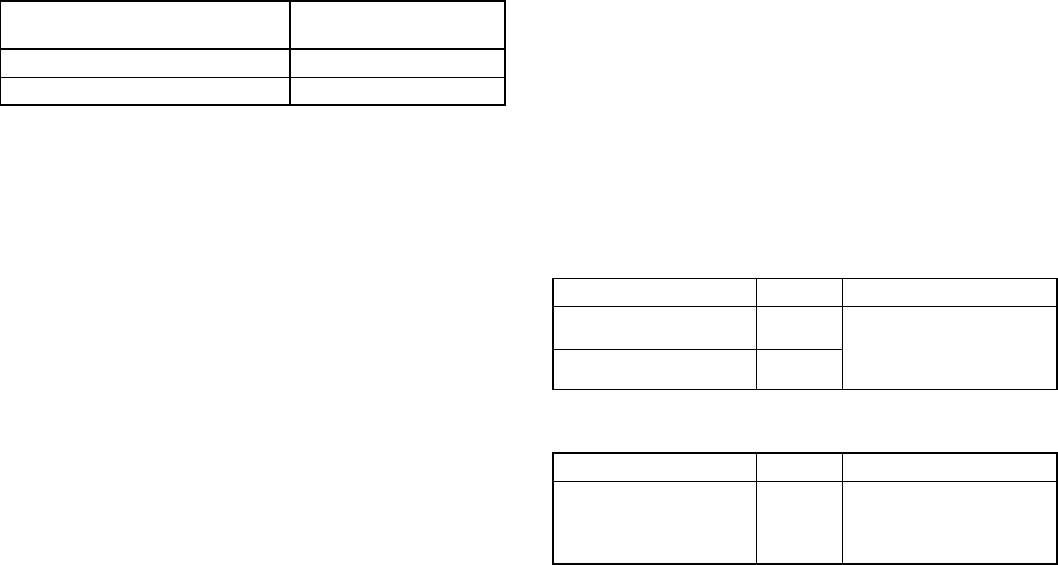
TABLE 11
SLP98DF Model
Maximum Over−Current
Protection (Amps)
07036B, 09036C, 09048C 15
09060C, 11060C 20
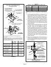
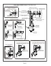
2 − Holes are on both sides of the furnace cabinet to facili-
tate wiring.
3 − Install a separate (properly sized) disconnect switch
near the furnace so that power can be turned off for
servicing.
4 − Before connecting the thermostat or the power wiring,
check to make sure the wires will be long enough for
servicing at a later date. Remove the blower access
panel to check the length of the wire.
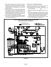
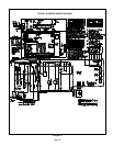
5 − Complete the wiring connections to the equipment.
Use the provided unit wiring diagram and the field wir-
ing diagram shown in figure 40 and table 14. Use
18−gauge wire or larger that is suitable for Class II ra-
ting for thermostat connections.
NOTE − Do NOT make a wire connection between
the room thermostat L terminal and the L terminal
of the SLP98DFV integrated control unless this is a
communicating thermostat installation with a non−
communicating outdoor unit.
6 − Electrically ground the unit according to local codes or,
in the absence of local codes, according to the current
National Electric Code (ANSI/NFPA No. 70) for the
USA and current Canadian Electric Code part 1 (CSA
standard C22.1) for Canada. A green ground wire is
provided in the field make−up box.
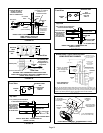
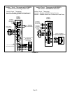
7 − One line voltage EAC" 1/4" spade terminal is provided
on the furnace integrated control. Any electronic air
cleaner rated up to one amp can be connected to this
terminal with the neutral leg of the circuit being con-
nected to one of the provided neutral terminals. See
figure 44 for location of terminal. This terminal is ener-
gized when the indoor blower is operating.
8 − One line voltage HUM" 1/4" spade terminal is provided
on the furnace integrated control. Any humidifier rated
up to one amp can be connected to this terminal with
the neutral leg of the circuit being connected to one of
the provided neutral terminals. See figure 44 for loca-
tion of terminal. This terminal is energized in the heat-
ing mode when the indoor blower is is operating.
9 − One 24V H" terminal is provided on the furnace inte-
grated control terminal block. Any humidifier rated up
to 0.5 amp can be connected to this terminal with the
ground leg of the circuit being connected to either
ground or the C" terminal. See figure 44 for location of
terminal.
10 −Install the room thermostat according to the instruc-
tions provided with the thermostat. See table 14 for
thermostat connections. If the furnace is being
matched with a heat pump, refer to the instruction
packaged with the dual fuel thermostat.
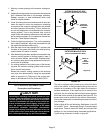
NOTE − The discharge air temperature sensor is intended
to be mounted downstream of the heat exchanger and air
conditioning coil. It must be placed in free airflow, where
other accessories (humidifiers, UV lights etc.) will not inter-
fere with its accuracy. Wiring distance between the furnace
and discharge air sensor should not exceed 10 ft. when
wired with 18−gauge thermostat wire.
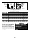
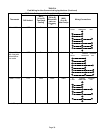
TABLE 12
Run Length Ċ Non Communicating
Wire Run Length AWG # Insulation/Core Types
Less than 100’ (30m) 18
Color−coded, temperature
rating 95
º
F (35
º
C) mini-
mum, solid core. (Class II
Rated Wiring)
More than 100’ (30m) 16
TABLE 13
Run Length Ċ Communicating
Wire Run Length AWG # Insulation/Core Types
Maximum length of wiring
for all connections on the
RSBus is limited to 1500
feet (457 meters).
18
Color−coded, temperature
rating 95
º
F (35
º
C) mini-
mum, solid core. (Class II
Rated Wiring)
Thermostat Selection
The SLP98DFV is designed to operate in a variable rate ca-
pacity mode using a two−stage thermostat. The SLP98DFV
will automatically adjust firing rate based upon thermostat
cycle times.
The icomfort Toucht thermostat must be used in commu-
nicating applications. Refer to the instructions provided
with the thermostat for installation, set−up and operation.
For optimal performance in non−communicating applica-
tions, Lennox recommends use of a ComfortSense
®
7000
high quality electronic digital thermostat or any other with
adjustable settings for 1st stage / 2nd stage on / off differen-
tials and adjustable stage timers.
Lennox recommends the following two−stage thermostat
set−up for optimal variable rate capacity mode:
First heat stage differential set to 1/2 to 1 degree F; second
heat stage differential set to 1/2 or 1 degree F; second heat
stage upstage timer disabled, or set to maximum (1 hr mini-
mum).
Indoor Blower Speeds
NOTE − When the SLP98DFV is used with icomfort
Toucht thermostat, proper indoor blower speed selec-
tions are made by the communicating thermostat.