


Page 27
1 − Seal any unused openings in the common venting sys-
tem.
2 − Inspect the venting system for proper size and horizontal
pitch. Determine that there is no blockage, restriction,
leakage, corrosion, or other deficiencies which could
cause an unsafe condition.
3 − Close all building doors and windows and all doors be-
tween the space in which the appliances remaining
connected to the common venting system are located
and other spaces of the building. Turn on clothes dry-
ers and any appliances not connected to the common
venting system. Turn on any exhaust fans, such as
range hoods and bathroom exhausts, so they will oper-
ate at maximum speed. Do not operate a summer ex-
haust fan. Close fireplace dampers.
4 − Follow the lighting instructions. Turn on the appliance
that is being inspected. Adjust the thermostat so that
the appliance operates continuously.
5 − After the main burner has operated for 5 minutes, test
for leaks of flue gases at the draft hood relief opening.
Use the flame of a match or candle.
6 − After determining that each appliance connected to the
common venting system is venting properly, (step 3)
return all doors, widows, exhaust fans, fireplace damp-
ers, and any other gas−burning appliances to their pre-
vious mode of operation.
7 − If a venting problem is found during any of the preced-
ing tests, the common venting system must be modi-
fied to correct the problem.
Resize the common venting system to the minimum
vent pipe size determined by using the appropriate
tables in Appendix G. (These are in the current stan-
dards of the National Fuel Gas Code ANSI Z223.1.
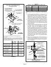
Electrical
ELECTROSTATIC DISCHARGE (ESD)
Precautions and Procedures
CAUTION
Electrostatic discharge can affect electronic com-
ponents. Take precautions during furnace installa-
tion and service to protect the furnace’s electronic
controls. Precautions will help to avoid control ex-
posure to electrostatic discharge by putting the fur-
nace, the control and the technician at the same
electrostatic potential. Neutralize electrostatic
charge by touching hand and all tools on an un-
painted unit surface, such as the gas valve or blower
deck, before performing any service procedure.
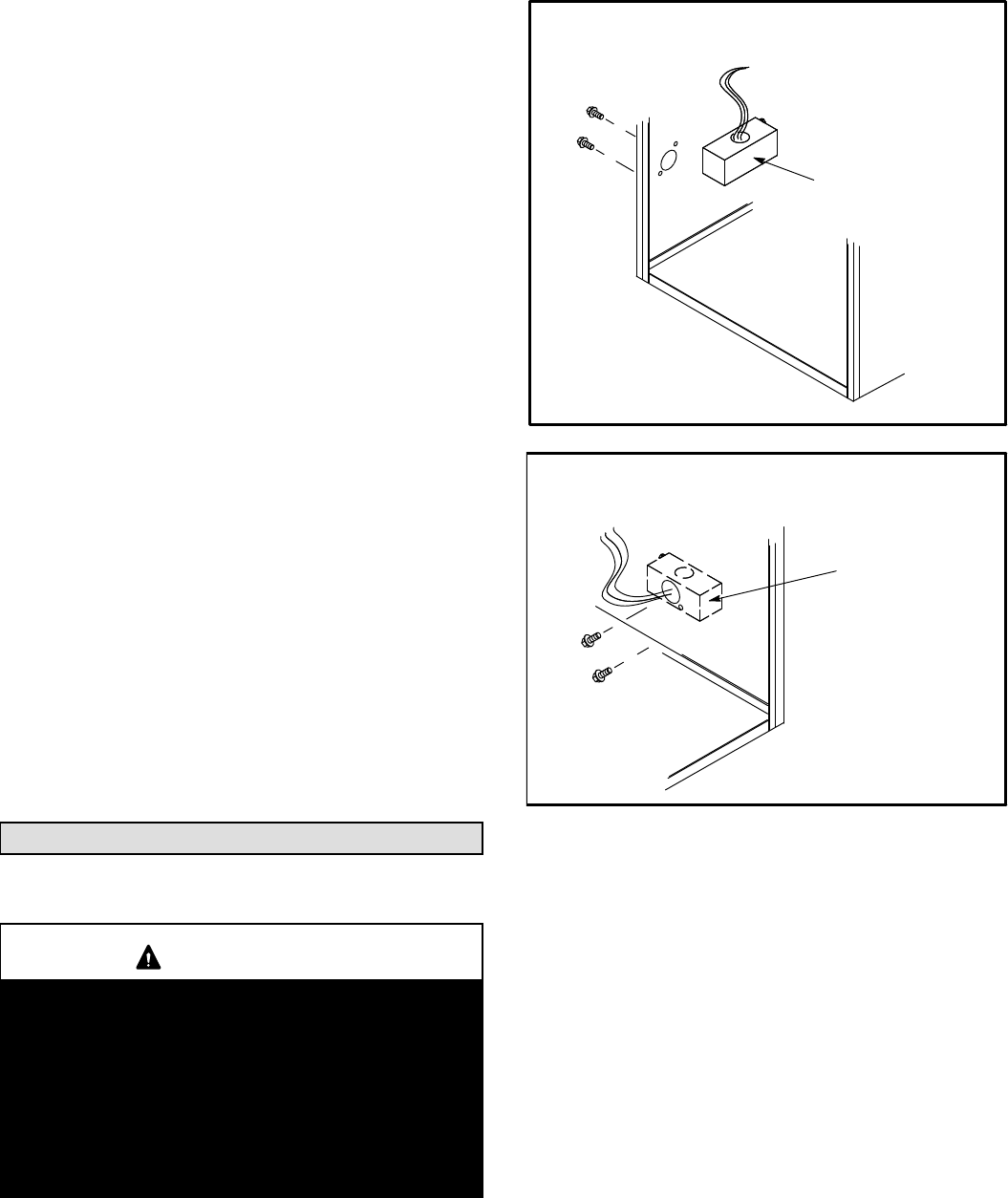
FIGURE 38
MAKE−UP
BOX INSIDE
CABINET
Left side
INTERIOR MAKE−UP BOX
(FACTORY− INSTALLED LEFT SIDE)
FIGURE 39
MAKE−UP
BOX
OUTSIDE
CABINET
Right Side
EXTERIOR MAKE−UP BOX
(FIELD PROVIDED RIGHT SIDE)
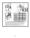
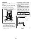
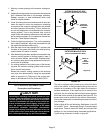
The unit is equipped with a make−up box on the left hand
side of the cabinet. A field−provided make−up box can be
installed on the exterior of the right side of the furnace to
facilitate installation. If the make−up box is moved to the
right side, clip the wire ties that bundle the wires together
and install on the outside of the cabinet. See figure 39. The
excess wire must be pulled into the blower compartment.
Secure the excess wire to the existing harness to protect it
from damage.
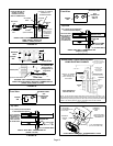
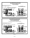
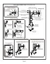
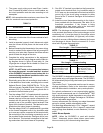
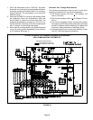
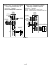
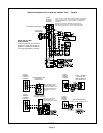
Refer to figure 40 for unit field wiring. See figures 41 and 42
for icomfort Toucht thermostat wiring in communicating
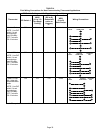
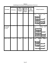
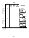
applications. Table 14 shows DIP switch and on−board link
settings for non−communicating thermostat applications.
Typical wiring schematic is shown in figure 43.