


Page 18
Details of Intake and Exhaust Piping Terminations for
Direct Vent Installations
NOTE − In Direct Vent installations, combustion air is tak-
en from outdoors and flue gases are discharged to out-
doors.
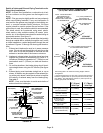
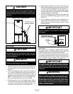
NOTE − Flue gas may be slightly acidic and may adversely
affect some building materials. If any vent termination is
used and the flue gasses may impinge on the building ma-
terial, a corrosion−resistant shield (minimum 24 inches
square) should be used to protect the wall surface. If the
optional tee is used, the protective shield is recommended.
The shield should be constructed using wood, plastic,
sheet metal or other suitable material. All seams, joints,
cracks, etc. in the affected area should be sealed using an
appropriate sealant. See figure 21.
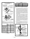
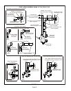
Intake and exhaust pipes may be routed either horizontally
through an outside wall or vertically through the roof. In attic
or closet installations, vertical termination through the roof
is preferred. Figures 19 through 28 show typical termina-
tions.
1 − Exhaust and intake exits must be in same pressure
zone. Do not exit one through the roof and one on the
side. Also, do not exit the intake on one side and the
exhaust on another side of the house or structure.
2 − Intake and exhaust pipes should be placed as close
together as possible at termination end (refer to il-
lustrations). Maximum separation is 3" (76mm) on roof
terminations and 6" (152mm) on side wall termina-
tions.
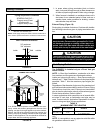
3 − On roof terminations, the intake piping should termi-
nate straight down using two 90° elbows (See figure
19).
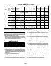
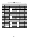
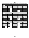
4 − Exhaust piping must terminate straight out or up as
shown. A reducer may be required on the exhaust pip-
ing at the point where it exits the structure to improve
the velocity of exhaust away from the intake piping.
See table 9.
NOTE − Care must be taken to avoid recirculation of
exhaust back into intake pipe.
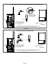
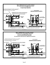
FIGURE 19
UNCONDITIONED
ATTIC SPACE
1/2" (13mm) FOAM
INSULATION IN
UNCONDITIONED
SPACE
SIZE TERMINATION
PIPE PER TABLE 9.
3"(76mm) MAX.
12" (305mm) ABOVE
AVERAGE SNOW
ACCUMULATION
3" (76mm) OR
2" (51mm) PVC
PROVIDE SUPPORT
FOR INTAKE AND
EXHAUST LINES
8" (203mm) MIN
Inches(mm)
DIRECT VENT ROOF TERMINATION KIT
(15F75 or 44J41)
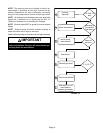
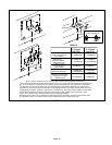
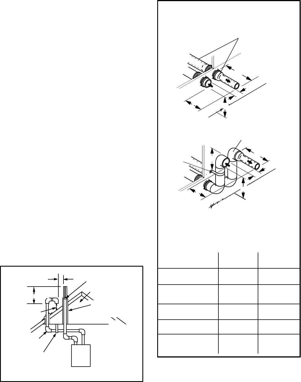
FIGURE 20
FIELD−SUPPLIED WALL TERMINATION OR
(15F74) WALL RING TERMINATION KIT
See venting table 7 for maximum venting lengths with this
arrangement.
* Use wall support every 24" (610 mm). Use two wall supports if
extension is greater than 24" (610 mm) but less than 48" (1219
mm). NOTE − One wall support must be 6" (152 mm) from top
of each pipe (intake and exhaust).
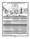
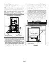
2" (51mm)
Vent Pipe
3" (76mm)
Vent Pipe
A−Minimum clearance
above grade or average
snow accumulation
B−Maximum horizontal
separation between
intake and exhaust
C−Minimum from
end of exhaust to
inlet of intake
D−Maximum exhaust
pipe length
E−Maximum wall support
distance from top of each
pipe (intake/exhaust)
12" (508MM) 12" (508MM)
6" (152MM) 6" (152MM)
8" (203MM) 8" (203MM)
12" (305MM) 20" (508MM)
6" (152MM) 6" (152MM)
NOTE − FIELD−PROVIDED
REDUCER MAY BE
REQUIRED TO ADAPT
LARGER VENT PIPE SIZE
TO TERMINATION.
D
B
C
SIZE TERMINATION
PER TABLE 9
1/2" (13mm) ARMAFLEX
INSULATION IN
UNCONDITIONED SPACE
STRAIGHT
APPPLICATION
B
C
A
D
* WALL
SUPPORT
1/2" (13mm) ARMAFLEX INSULATION
IN UNCONDITIONED SPACE
E
EXTENDED
APPLICATION
A