


NOTE: DIAGRAMS & ILLUSTRATIONS ARE NOT TO SCALE
9
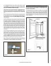
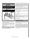
It is recommended that the burner height, where possible, should
be approximately 4 ft. from the floor. This will give the best viewing
position. When selecting the height, ensure that the clearance to the
ceiling is 32" minimum, as specified on
Page 6.
After selecting the final mounting position of the appliance, taking into
account the site requirements as specified in Section 9.0 of these
instructions, the integrity of the wall, and the feasibility of the proposed
supply pipe routing, the firebox of the appliance may be secured to the
wall.
Due to the weight of the front surround assembly, it is possible to fasten
the outer casing to the wall in up to nine positions, depending on the
strength/condition of the wall. If in doubt always use extra fixings!
Use a bubble level to ensure that the outer casing is level at all times
during installation.
Insert the screws into two of the upper holes, leaving 3/16" protruding
from the wall. Temporarily hang the outer casing on the wall, and mark
any additional fixing points as required. If the appliance is to be fitted
to a lightly colored wall, it is advantageous to paint this wall area with
black or dark paint in the vicinity of the lower rectangular slots on the
outer casing. This will mask the wall when viewed from the front of the
appliance. Ensure paint is fully dry before mounting the appliance. Use
the outer casing as a template to mark this area on the wall. Remove
the outer casing from the wall and drill holes for the additional fixing
points as required. Insert either wall plugs or cavity screw fixings as
required. Re-position the outer casing on the wall and using a bubble
level to check the casing is square and level, tighten all of the fixing
screws fully.
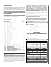
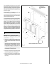
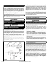
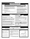
Now, with the outer casing fixed to the wall, the main firebox can be
secured in position. The firebox is held on the outer casing using four
studs and two normal nuts (upper fixings) and two wing nuts (lower
fixings). Make sure that the upper nuts are unscrewed approximately
one turn from the fully tightened position in order to create a 1/16" gap
as shown in Figure 4. The firebox may now be hung onto the top studs,
and then pushed onto the lower studs so that the lower studs protrude
through the lower fixing holes in the back panel of the firebox.
Next, re-fit the grill, the indicator bracket and the control knob and
spindle, and secure in position using the correct fixing screws (re-fitting
is the opposite of removal as detailed in these instructions).
Figure 4
1/16"
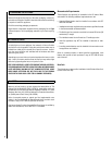
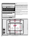
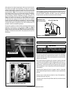
13.0 FITTING THE SURROUND ASSEMBLY
Due to the weight of the frame assembly, it is recommended to seek
assistance for this operation.
The frame assembly will be supported by keyhole slots by four M6
screws which protrude from the front of the outer casing (see Figure 5)
. Ensure each screw is unscrewed approximately one turn from the fully
screwed in position in order to create a 1/16" gap (shown). Hang the
surround assembly onto the outer casing, starting with the two bottom
fixings, ensuring that the corresponding keyhole shaped holes engage
the screw heads fully.
Figure 5
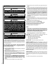
Heat Shield
IMPORTANT NOTE: Ensure that the
surround is positioned with the
heat shield on top as shown.