


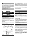
10 NOTE: DIAGRAMS & ILLUSTRATIONS ARE NOT TO SCALE
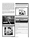
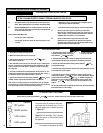
14.0 CHECKING THE BURNER
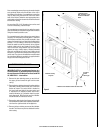
There are no imitation fuel bed components, such as logs or rocks,
to install. The appliance features a ribbon burner which is designed to
produce a continuous band of flame over its length. The burner should
be visually inspected to ensure it is free from any foreign matter. If it is
necessary to clean or dust off the burner then the glass door should be
removed by removal of the four retaining screws. Re-fit the glass door
after cleaning or inspection, ensuring a good seal.
15.0 CONNECTING A GAS LINE
A qualified gas appliance installer must connect the gas room heater to
the gas supply. Consult all local codes.
The installer must provide an ANSI approved manual shut off valve, flex
connector and 3/8" NPT fitting. A flex gas line kit with shut-off valve is
available (see Page 16 or ordering information).
Route gas line using techniques and materials prescribed by local
and/or national codes. Only use pipe of 1/2" or greater size to allow full
gas volume to the gas fireplace. Undue pressure loss will occur if the
pipe is too small.
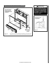
An external regulator must be used on all propane (L.P.G.) heaters, in
addition to the regulator fitted to the heater, to reduce the supply tank
pressure to 13" w.c. (maximum).
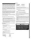
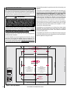
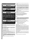
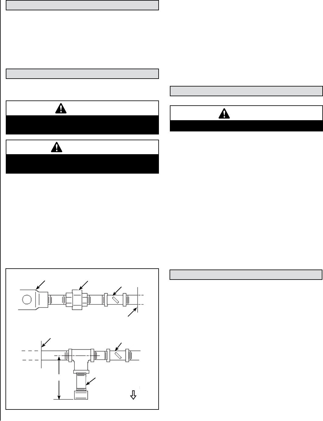
Regulator
Manual
Shut-Off
Valve
Union
Sediment
Trap
Fireplace or
Firebox Wall
Wall
Shut-Off
Key
Fireplace or
Firebox Wall
Down
3"
Figure 6
WARNING
Connecting directly to a unregulated propane (L.P.G.)
tank may cause an explosion.
An ANSI approved manual shut-off valve and union must be installed
upstream of the heater within the fireplace cavity when rigid pipe is
used. Ensure that a sediment trap is installed upstream of the heater
(Figure 4) within the structure’s piping system to prevent moisture
and contaminants from passing through the pipe to the heater controls
and burner. Failure to do so could prevent the heater from operating
reliably.
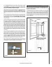
The heater gas inlet connection is 3/8” NPT at the regulator, located
below the burner, in the right hand side of the heater. When tightening
up the joint to the regulator hold the regulator securely with a wrench
to prevent the regulator from moving.
IMPORTANT
Hold heater regulator with a wrench to prevent move-
ment when connecting to inlet piping.
16.0 CHECKING THE GAS CONNECTIONS
Turn on gas supply and test for gas leaks using a gas leak test solution
(also referred to as bubble leak solution).
NOTE: Using a soapy water solution (50% dish soap, 50% water) is
an effective leak test solution, but it is not recommended, because the
soap residue that is left on the pipes/fittings can result in corrosion
over time.
A. Light the appliance (refer to the lighting instructions label in the control
compartment or on Page 14).
B.
Brush all joints and connections with the gas leak test solution to
check for leaks. If bubbles are formed, or gas odor is detected, turn
the gas control knob (off/pilot/on) to the “OFF” position. Either tighten
or refasten the leaking connection, then retest as described above.
C.
When the gas lines are tested and leak free, be sure to rinse off the
leak testing solution.
D.
Observe the individual tongues of flame on the burner. Make sure all
ports are open and producing flame evenly across the burner. If any
ports are blocked, or partially blocked, clean out the ports.
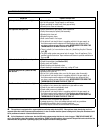
17.0 GAS PRESSURE CHECK
WARNING
Never use an open flame to check for leaks.
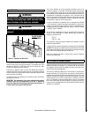
Checking Manifold Pressure at Provided Test Point (see Figure 7a) -
The pressure test point is located on the left hand side of the appliance,
on the main burner pipe, next to the brass restrictor adjacent to the
front left hand side burner bracket. Release the setting pressure test
point screw, and attach a U gauge. Light the fire on the HIGH setting.
Checking Manifold and Inlet Pressure at Valve (see Figure 7b) - The
heater regulator controls the burner pressure which can be checked at
the pressure test points located on the control valve itself for burner
(manifold) and regulator (inlet) setting pressures.
The valve is located on the lower right side of the appliance (see
exploded view drawing on Page 17). Release the test point screws and
ensure operating pressures are as specified in Table 1 on Page 3 of
these instructions. The pressure should be checked with the gas heater
burning and the control set to high flame.
NOTE: See Page 19 for gas line entry point dimensions.