


7
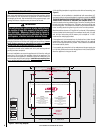
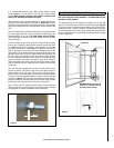
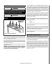
Non-concealed gas connections may be made using the
entry points at either end of the firebox or the one in
the bottom of the firebox. A concealed gas connection
may be made using the knock out hole in the center
back of the firebox. Select the most appropriate entry
point and knock out the relevant hole in both the firebox
and the outer casing.
No more than 59" of 1/4" diameter pipe must be used
to avoid unnecessary pressure drops.
If a concealed gas connection is to be made, the supply
pipe should always be sleeved through walls and floors
using the shortest possible route.
For concealed supply pipe routing, pipes must (where
possible) be vertical and providing there is sufficient
wall thickness available, they should be placed in pipe
chases. Horizontal pipe runs should be avoided where
possible. Prior to chasing a solid wall, an inspection
should be made to note the proximity of any cables/
sockets outlets which may already be buried. Pipes
must be secured using suitable clips and protected
against corrosion. Ideally factory finished protected
pipe-work and fittings should be used. Joints should
be kept to a minimum and compression fittings must
not be used. The pipe-work installation must be tested
for soundness before any protection is applied and/or
the pipe-work and fittings are buried.
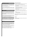
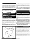
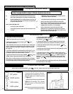
1. Remove the Grill.
Note: This design of grill
not fitted to widescreen
model
2. Remove retaining
wing nuts
3. Remove
spindle
retaining pin
4. Remove control indicator bracket and control knob
Note : X-Fire 1000
shown as example
5. Widescreen
models : Remove
two self-tapping
screws from the
Left hand side of
the outer casing
and one from the
right hand side.
NOTE: DIAGRAMS & ILLUSTRATIONS ARE NOT TO SCALE
Figure 2
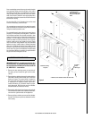
11.0 PREPARING THE APPLIANCE
IMPORTANT NOTE: All gas piping must be done by a
licensed plumber or gas fitter and must conform to
the requirements of the National Fuel Gas Code NFPA
54 / ANSI Z223.1 - latest edition.
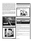
1. Remove the two retaining screws on each side of
the upper grill and remove the grill from the outer
casing.
2. Remove the two retaining wing nuts from the retaining
studs that protrude into the lower part of the main
firebox as shown. The control knob is located on
the lower right hand side of the outer casing, and
is mounted in an indicator bracket, which has a
metallic indication ‘pip’ (indication mark for proper
knob alignment). Both the knob and the indicator
bracket should be removed as follows;
3. Remove the retaining pin from the gas valve spindle
and withdraw the control knob and the spindle exten-
sion from the right hand side of the appliance.
4. Remove the four retaining screws and the indicator
bracket. The firebox may now be detached from the
outer casing.