


7
Non-concealed gas connections may be made using the
entry points on the base of the firebox. A concealed gas
connection may be made using the knockout hole in the
center back of the firebox. Select the most appropriate
entry point and knock out the relevant hole.
No more than 59" of 1/4" diameter pipe must be used
to avoid unnecessary pressure drops.
If a concealed gas connection is to be made, the supply
pipe should always be sleeved through walls and floors
using the shortest possible route.
For concealed supply pipe routing, pipes must (where
possible) be vertical and providing there is sufficient
wall thickness available, they should be placed in pipe
chases. Horizontal pipe runs should be avoided where
possible. Prior to chasing a solid wall, an inspection
should be made to note the proximity of any cables/
sockets outlets which may already be buried. Pipes
must be secured using suitable clips and protected
against corrosion. Ideally factory finished protected
pipe-work and fittings should be used. Joints should
be kept to a minimum and compression fittings must
not be used. The pipe-work installation must be tested
for soundness before any protection is applied and/or
the pipe-work and fittings are buried.
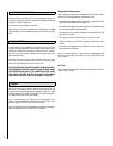
NOTE: DIAGRAMS & ILLUSTRATIONS ARE NOT TO SCALE
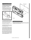
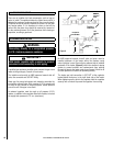
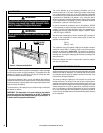
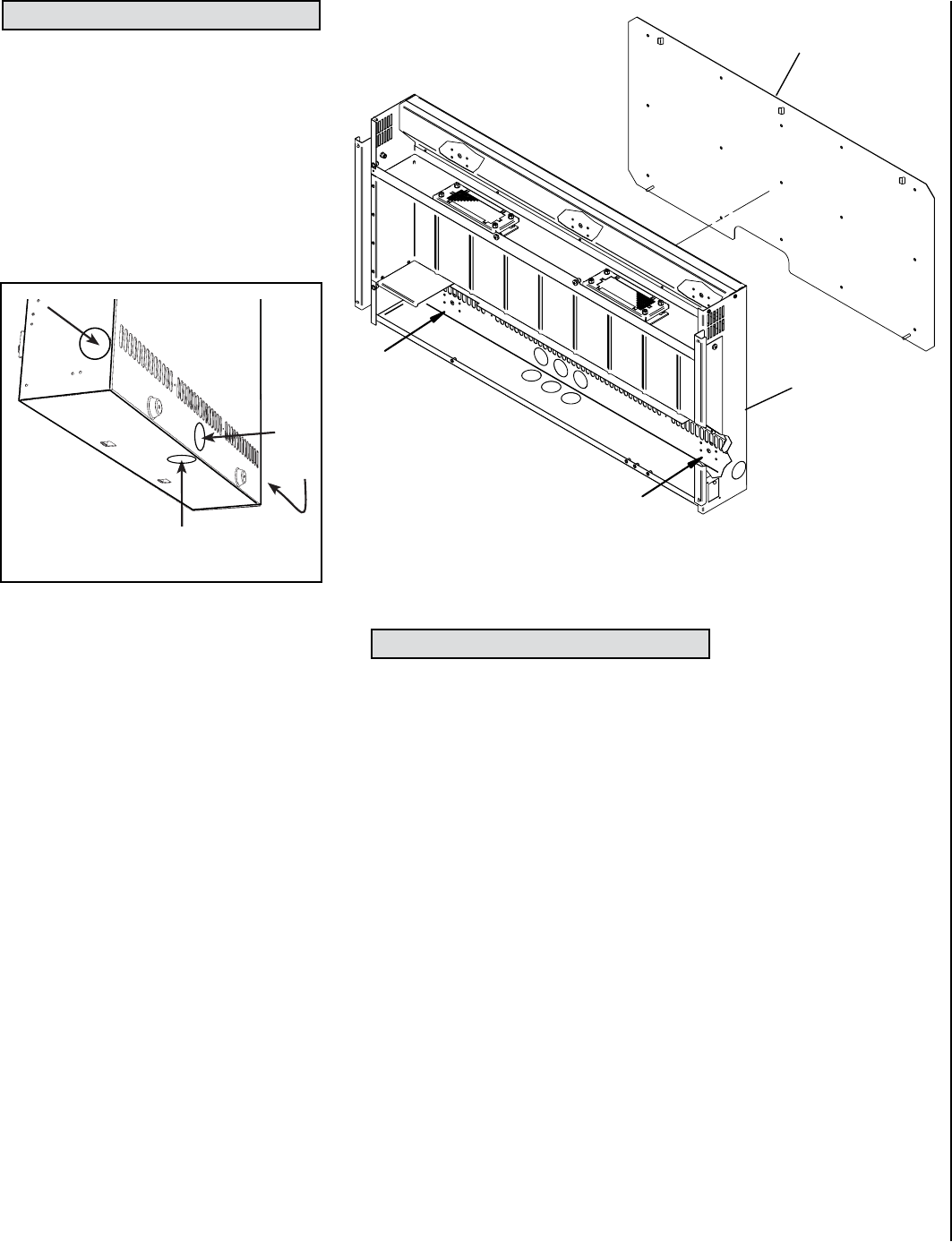
Remove the wall mounting plate from the back of the appliance firebox by removing the
two retaining wing nuts (indicated by arrows in Figure 2) from the retaining studs that
protrude into the lower part of the main firebox.
11.0 PREPARING THE APPLIANCE
Figure 2
Wall Mounting Plate
Firebox
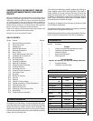
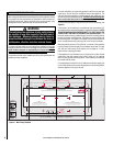
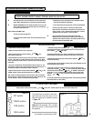
10.0 GAS SUPPLY ROUTES
IMPORTANT NOTE: All gas piping must be done by
a licensed plumber or gas fitter and must conform
to the requirements of the National Fuel Gas Code
NFPA 54 / ANSI Z223.1 - latest edition.
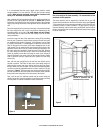
Gas connection: The heater gas inlet connection is
3/8” NPT at the regulator, located below the burner,
in the right hand side of the heater. There are four
possible entry points for the gas supply pipe-work
to enter the appliance firebox. These entry points
are ‘knock out’ type holes (shown in Figure 1).
Figure 1 - Gas Supply Entry Points