


11
NOTE: DIAGRAMS & ILLUSTRATIONS ARE NOT TO SCALE
16.0 CHECKING THE GAS CONNECTIONS
Turn on gas supply and test for gas leaks using a gas leak test solution
(also referred to as bubble leak solution).
NOTE: using a soapy water solution (50% dish soap, 50% water) is
an effective leak test solution, but it is not recommended, because the
soap residue that is left on the pipes/fittings can result in corrosion
over time.
A. Light the appliance (refer to the lighting instructions label in the control
compartment or on Page 15).
B.
Brush all joints and connections with the gas leak test solution to
check for leaks. If bubbles are formed, or gas odor is detected, turn
the gas control knob (off/pilot/on) to the “OFF” position. Either tighten
or refasten the leaking connection, then retest as described above.
C.
When the gas lines are tested and leak free, be sure to rinse off the
leak testing solution.
D.
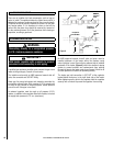
Observe the individual tongues of flame on the burner. Make sure all
ports are open and producing flame evenly across the burner. If any
ports are blocked, or partially blocked, clean out the ports.
17.0 GAS PRESSURE CHECK
WARNING
Never use an open flame to check for leaks.
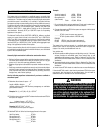
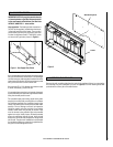
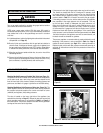
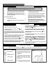
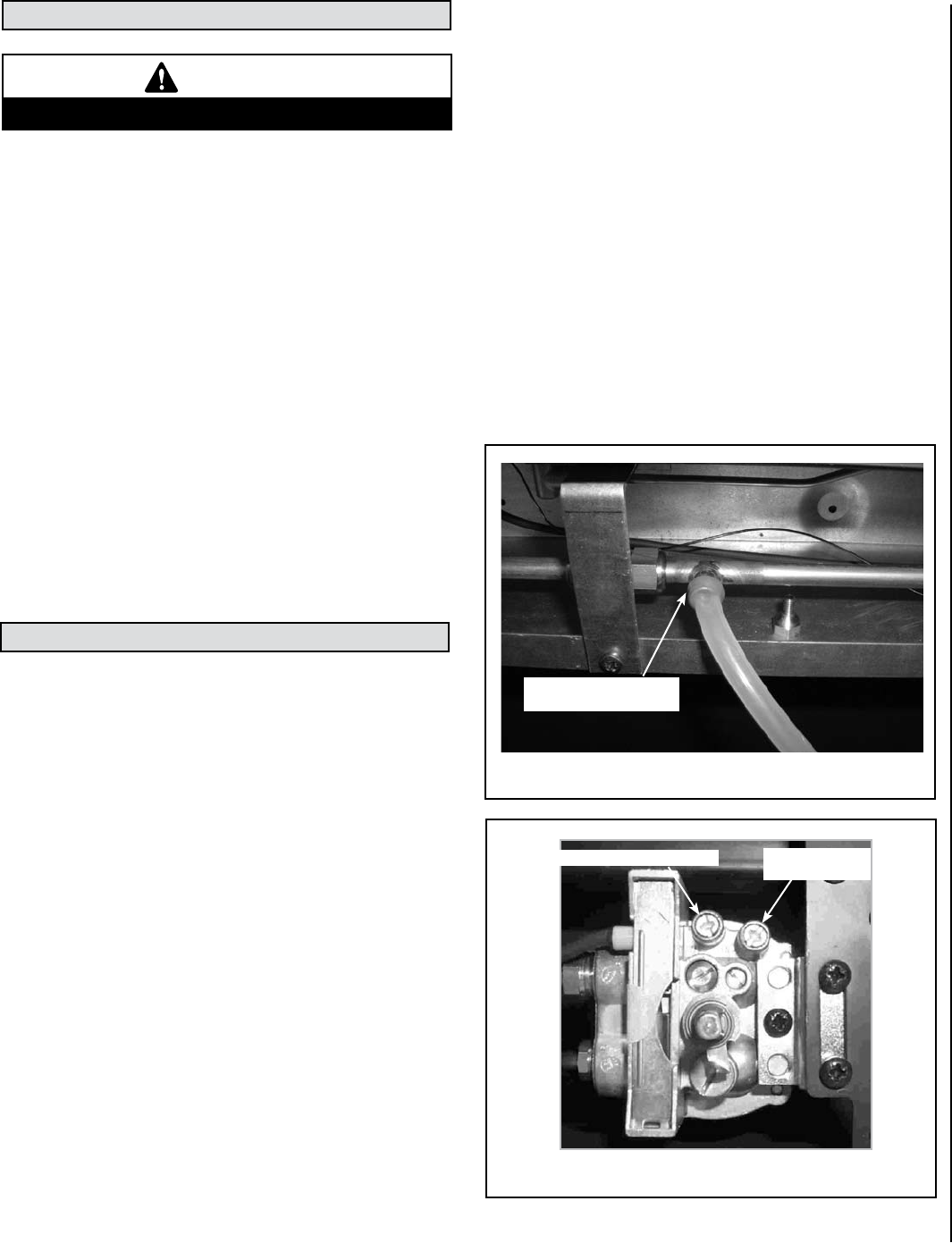
Checking Manifold Pressure at Provided Test Point (see Figure 7a) -
The pressure test point is located on the left hand side of the appliance,
on the main burner pipe, next to the brass restrictor adjacent to the
front left hand side burner bracket. Release the setting pressure test
point screw, and attach a U gauge. Light the fire on the HIGH setting.
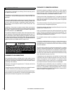
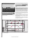
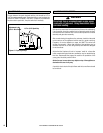
Checking Manifold and Inlet Pressure at Valve (see Figure 7b) - The
heater regulator controls the burner pressure which can be checked at
the pressure test points located on the control valve itself for burner
(manifold) and regulator (inlet) setting pressures.
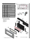
The valve is located on the lower right side of the appliance (see
exploded view drawing on Page 17). Release the test point screws and
ensure operating pressures are as specified in Table 1 on Page 3 of
these instructions. The pressure should be checked with the gas heater
burning and the control set to high flame.
Figure 7a
Burner (Manifold) Pressure
Figure 7b - Manifold and Inlet Pressure Taps
Regulator (Inlet)
Pressure Setting
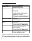
If the pressure is too high, the gas supply meter may be set incorrectly.
This should be checked with the fire running and if necessary reset
by the gas supplier. If the burner pressure is too low, then check the
inlet pressure with the appliance running. If this is less than the inlet
pressure stated in Table 1, it will need to be reset by the gas supplier.
If the setting pressure is too low, but the meter pressure is acceptable,
then a problem in the supply pipework is to be suspected. This may
be dirt and debris, kinked or inadequate size pipes, restriction in a
fitting, shut off elbow not fully open or solder flashing across a joint.
Identify the cause of the restriction and rectify. Switch the fireplace
off, disconnect the U gauge and refit the test nipple screw. Light the
fireplace and check test nipple for gas tightness. In the event that the
burner pressure is not in accordance with the figures stated in the Table
1 of these instructions, the appliance must not be commissioned, and
the dealer should be contacted for guidance.
The pressure regulator on manual models is preset and locked to avoid
tampering. If the pressure is not as specified in Table 1 on Page 3,
replace the burner assembly (see Page 17 for ordering information).
Replace the test point screws after pressure measurement ensuring no
gas leaks. All instructions must be left in the possession of the user for
safekeeping.
Pressure Test Point
(on left side of fireplace)