18
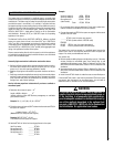
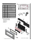
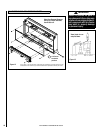
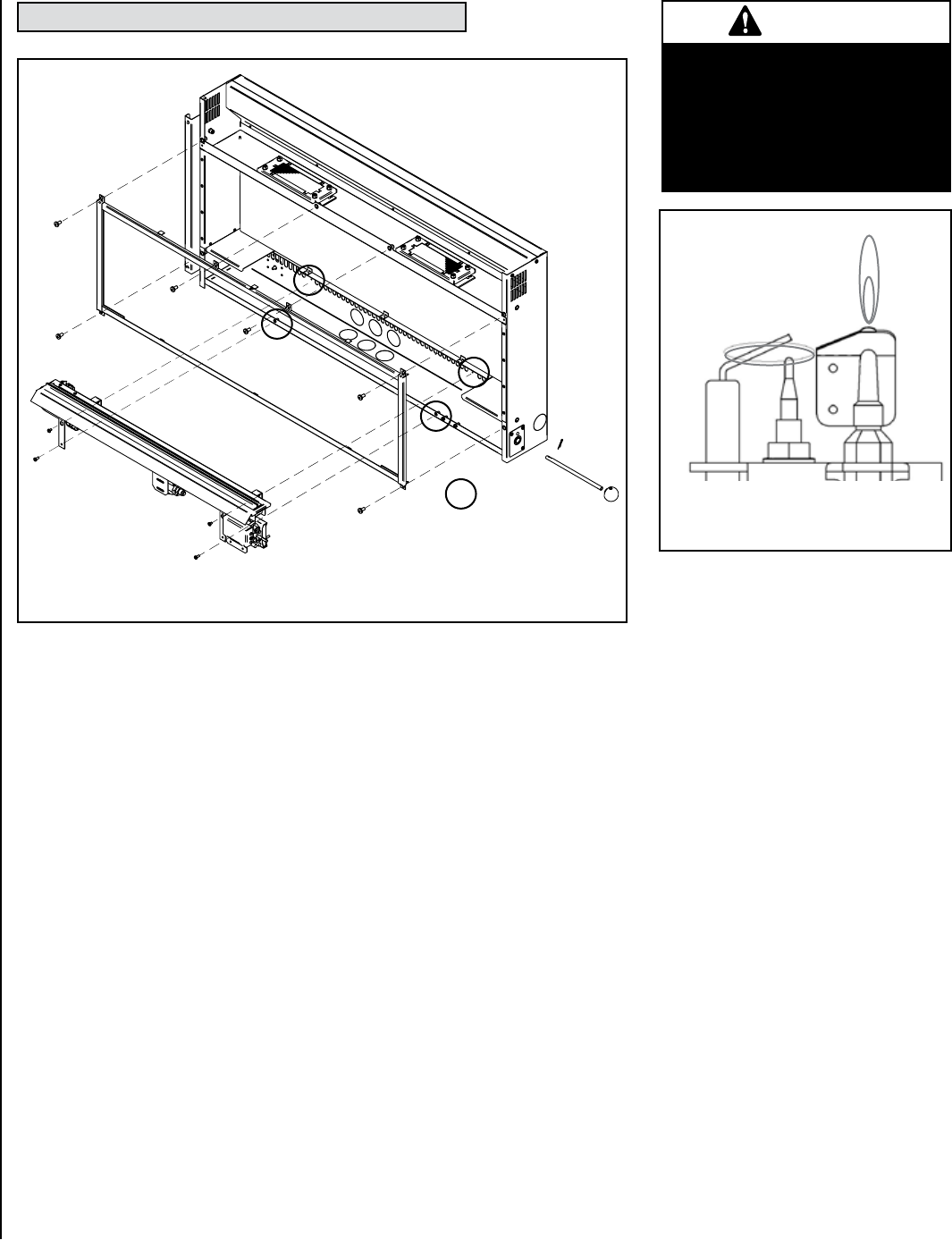
26.0 POSITIONING OF FIELD REMOVABLE PARTS
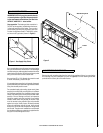
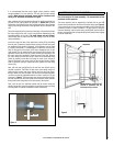
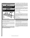
Glass Door Removal: Remove
the four (4) screws indicated,
then lift door off.
Figure 12
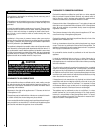
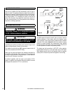
WARNING
Failure to position the parts in
accordance with these diagrams
or failure to use only parts specifi-
cally approved with this heater
may result in property damage
or personal injury.
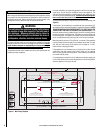
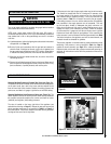
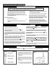
Figure 13
Visual check for cor-
rect pilot flame.
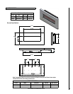
NOTE: DIAGRAMS & ILLUSTRATIONS ARE NOT TO SCALE
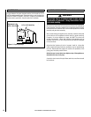
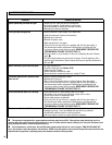
4 off burner
installation
positions
As our policy is one of continuous improvement and development, we hope therefore you will
understand we must retain the right to amend details and/or specifications without prior notice.


