


8
NOTE: DIAGRAMS & ILLUSTRATIONS ARE NOT TO SCALE.
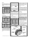
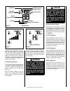
Gas Controls/Control Compartment Access
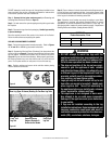
The gas control valve can be found behind the control compartment access door (Figure 2 ).
Removing Control Compartment Door:
The control compartment door sits in place below the front glass enclosure panel. The door sits
and is hinged on the lower cabinet frame. The door is held in place (closed) by magnets at the
right and left side. To open the door, insert a finger behind the door at the right or left side and
tilt the door forward. To close the door, simply push it up and back. To remove the door, grasp it
and pull it away from the fireplace.
OPERATION AND CARE OF YOUR APPLIANCE
WARNING
Young children should be carefully supervised when they are in the
same room as the appliance. Toddlers, young children and others
may be susceptible to accidental contact burns. A physical barrier is
recommended if there are at risk individuals in the house. To restrict
access to a fireplace or stove, install an adjustable safety gate to keep
toddlers, young children and other at risk individuals out of the room
and away from hot surfaces.
AVERTISSEMENT
Les jeunes enfants devraient être surveillés étroitement lorsqu’ils se trou-
vent dans la même pièce que l’appareil. Les tout petits, les jeunes enfants
ou les adultes peuvent subir des brûlures s’ils viennent en contact avec
la surface chaude. Il est recommandé d’installer une barrière physique
si des personnes à risques habitent la maison. Pour empêcher l’accès
à un foyer ou à un poêle, installez une barrière de sécurité; cette mesure
empêchera les tout petits, les jeunes enfants et toute autre personne à
risque d’avoir accès à la pièce et aux surfaces chaudes.
Figure 2
Andiron
Placement
Holes
Burner
Gas Valve
Gas Line Access
Below Firebox
Bottom
Air Shutter
Adjustment Lever
Intermittant/Standing
Pilot Mode Switch
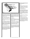
Remote Control System
The Remote and Receiver allows you to com-
mand the functions of your fireplace from
the comfort of you chair and is configured to
control the On/Off primary burner operation, its
flame levels (through six levels) and provides
On/Off and Smart thermostatic control of the
Symmetry appliance
The system controls fan speed through six (6)
levels and has a constantly powered 110V/60Hz
power outlet.
The Receiver connects directly to the gas valve,
stepper motor and the Fan Control Module with
and umbilical cord wiring harness (see Wire
Diagram on page 19).
The Receiver is powered by 4 AA type batteries,
located within.
The Receiver accepts commands via radio
frequency from the Transmitter and does not
require line-of-sight operation.
The Receiver three position slider switch can
be set to one of three positions: ON (Manual
Override), REMOTE (Remote Control) or OFF.
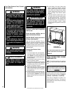
Initializing The System For The First Time
Install the 4 AA batteries into the receiver battery
bay (behind the wall switch plate).
Note: The polarity of the battery and insert
into the battery bay as indicated on the Battery
cover (+/-).
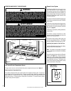
Place the 3 position slider switch in the "Remote"
position (see Figure 3 ). Using the end of a
paper clip, or other similar object, insert the
end of the paper clip into the hole marked "PRG"
on the Receiver front cover. The Receiver will
"beep" three (3) times to indicate that it is ready
to synchronize with a Transmitter.
Figure 3
Remote
Off
On
PRG
Slider Switch In
Remote Position