


18
NOTE: DIAGRAMS & ILLUSTRATIONS ARE NOT TO SCALE.
WARNINGS
• Air shutter adjustment should
only be performed by a quali-
fied professional service
technician.
• Ensure front glass panel are
in place and sealed during
adjustment.
CAUTIONS
• Carbon will be produced if the
air shutter is closed too much.
Any damage due to carboning
resulting from improperly
setting the air shutter is not
covered under the warranty.
• The air shutter door and nearby
appliance surfaces are hot.
Exercise caution to avoid
injury while adjusting flame
appearance.
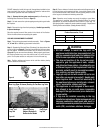
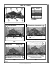
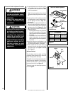
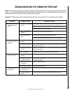
Burner Air Shutter Adjustment Procedure
1. Locate adjustment lever and adjust air shutter
to the standard setting as shown in Figure
17 (adjustment rod is located in the lower
control compartment).
Note: Pushing the adjustment lever back to
decrease air and pulling forward to increase
air.
2. Light appliance (follow lighting procedure
on lighting label in control compartment or
see the lighting instructions, Page 22 in
this manual).
3. Allow the burner to operate for at least 15 min-
utes while observing the flame continuously
to ensure that the proper flame appearance
has been achieved (see Figures 14, 15 or
16). If the following conditions are present,
adjust accordingly.
• Ifameappearsweakorsooty,adjustthe
air shutter, incrementally, to a more open
position until the proper flame appearance
is achieved.
• Ifamestaysloweredblue,adjusttheair
shutter, incrementally, to a more closed
position until the proper flame appearance
is achieved.
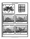
4. Leave the control knob (off/pilot/on) in the
ON position and the burner OFF/ON switch
OFF (and remote switches, if applicable).
5. When satisfied that the burner flame ap-
pearance is normal, close the lower control
compartment door (see Figures 14, 15 and
16 on Page 17).
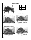
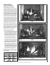
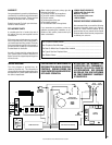
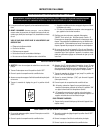
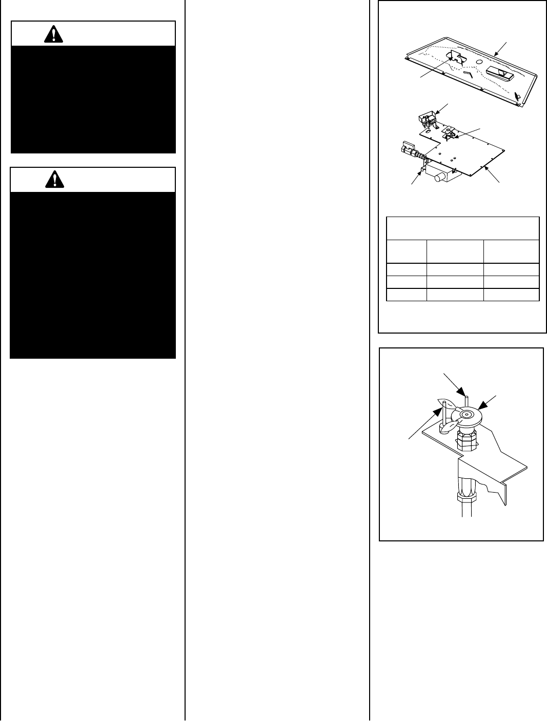
Appliance Checkout
The pilot flame should be steady, not lifting
or floating. Flame should be blue in color with
traces of orange at the outer edge.
The top 3/8" (10 mm) at the pilot generator (ther-
mopile) should be engulfed in the pilot flame.
The flame should project 1" (25 mm) beyond
the hood at both ports (see Figure 18).
To light the burner, refer to the lighting instruc-
tions on Page 22.
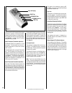
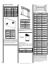
Burner Air Shutter Adjustment
Figure 17
MAIN BURNER
FACTORY SHUTTER OPENING SETTING
Models
Natural Gas
Inches (mm)
Propane Gas
Inches (mm)
SYM-35 3/16 (4.8) 7/16 (11.1)
SYM-40 3/16 (4.8) 3/8 (9.5)
SYM-45 3/16 (4.8) 3/8 (9.5)
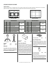
Burner Assembly
Gas Train
Assembly
Air Shutter
Adjustment Lever
Air Shutter
Adjustment Rod
View Air
Shutter
Pilot Assembly
Pilot
Hood
Sensor
Ignitor
Figure 18