9
NOTE: DIAGRAMS & ILLUSTRATIONS ARE NOT TO SCALE.
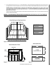
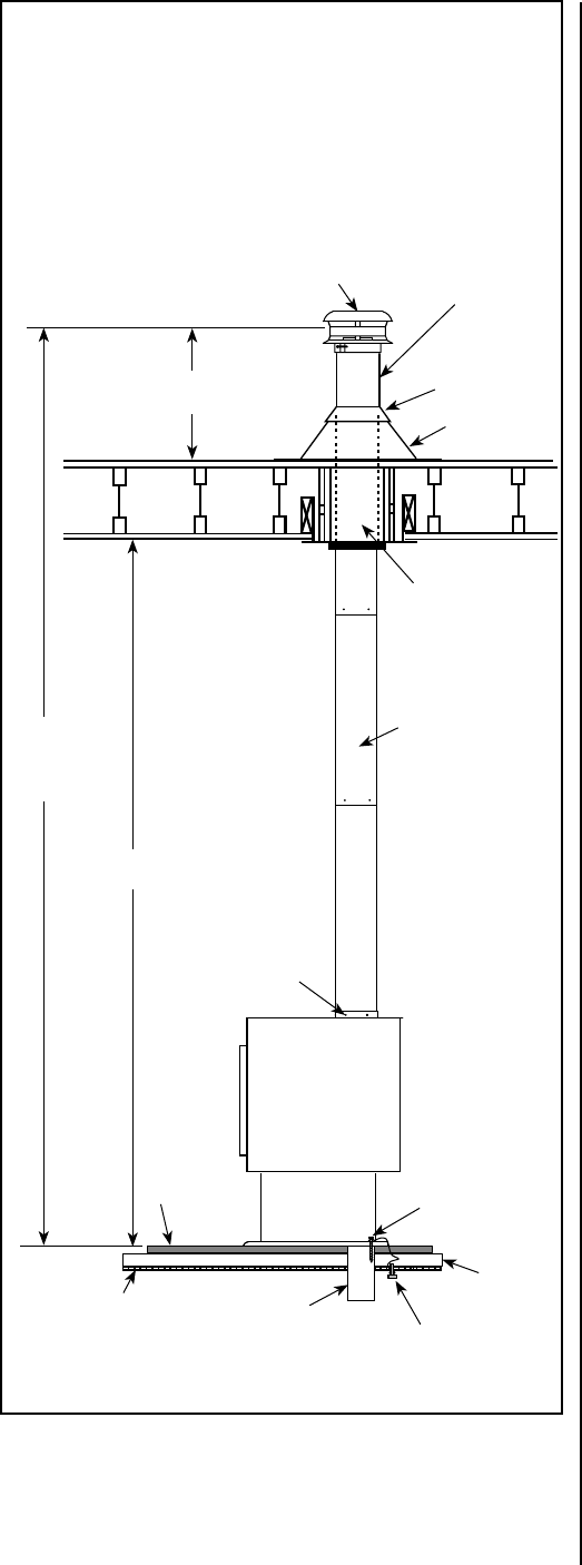
Manufactured Home Installations
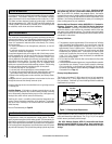
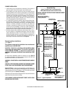
(ref. Figure 7)
This appliance is approved for installation into a manufactured
(mobile) home in the USA ONLY!
Installation should be in accordance with the Mobile Home
Construction and Safety Standard, Title 24 CFR, Part 3280 (in
Canada CAN/CSA Z240 MH), or, when such a standard is not
applicable, the Standard for Mobile Home Installations, ANSI
A225.1.
All mobile home installations require an outside air kit (see Page 28
for ordering information). The stove must be secured to the floor and
grounded to the chassis of the mobile home.
WARNING: DO NOT INSTALL IN SLEEPING ROOM OF A MOBILE
HOME.
CAUTION: THE STRUCTURAL INTEGRITY OF THE MOBILE HOME
FLOOR, WALL AND CEILING/ROOF MUST BE MAINTAINED.
Approved Chimney* - Your stove is approved for use with Class A, UL
103 HT (U.S.) / ULC-S629 (Canada) Listed Residential Type and Building
Heating Appliance Chimney (HT chimney - 2100° Fahrenheit) and double
wall connector pipe from Security™ Chimneys.
Clearances to connector shall be measured from 6” flue collar. Restrictions
apply! Read instructions before installing.
YOUR CHIMNEY INSTALLATION MUST COMPLY WITH LOCAL
BUILDING AND FIRE CODES.
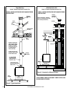
Termination Cap
with Spark Arrestor
Remove, if mobile
home is transported
Storm
Collar
Flashing
Support
Box
DVL Close
Clearance
Connector Pipe
Floor
Protector
3 Feet
Minimum
7 Feet
Minimum
Double Wall Pipe
Using 6” Diameter Type L-Vent Connector Pipe
Mobile (Manufactured) Home Installation Shown
Figure 7 - Typical Installation
Minimum of
12-15’ of Flue
to achieve a
stable draft.
Fasten each stove pipe
connection with at least
3 sheet metal screws.
Mobile home installations
require a spark arrestor at the
chimney termination.
All mobile home installa-
tions require an outside
air kit (see Page 28 for
ordering information)
and the stove must be
secured to the floor and
grounded to the mobile
home chassis.
Install Outside Air
Kits per instructions
on Page 11
INSTALL VENTING SYSTEM PER VENT MANUFACTURERS
INSTRUCTIONS!
Fasten stove pipe to
flue collar using 3
sheet metal screws.
Secure Stove
to floor
Grounded to Steel Chassis
using a #8 AGW copper
wire or equivalent.
Chassis
Floor
CHIMNEY INSTALLATION
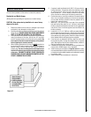
• Install chimney as per manufacturer’s instructions. Some brands of
pipe may require removal of the spacer ring in the flue collar.
• All horizontal runs of pipe should be as short as possible and are
required by NFPA No. 211 to have an upward pitch or rise in the same
direction the smoke travels of no less than 1/4” to the linear foot. The
connector pipe must meet minimum clearances in any direction to
walls or other combustible materials. It must attach to a listed double
wall metal chimney at least 6” in diameter or to a masonry chimney
with a flue passage of at least 48 square inches.
• It is required that a chimney connector pipe not extend further than
the inner wall of the flue when it is connected to a masonry chimney
and that it either be cemented to the masonry or be installed without
cement in a thimble connected to the masonry wall. When the
connector is inserted into a thimble, the joint must be tight enough
so that it will not be dislodged in normal use. Install connector at
no less than the minimum clearances from the ceiling when using a
90-degree elbow to pass through combustible constructions.
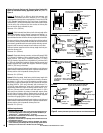
• Chimney connector pipes should never pass through a floor, ceiling,
fire wall, partition, or combustible construction of any type unless
certain precautions are taken. The best method is to use a listed
thimble and a listed chimney in accordance with the manufacturer’s
directions. NFPA No. 211 gives approved methods for passing a flue
pipe through combustible constructions (see Page 10).
Stove
Side View


