


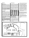

NOTE: DIAGRAMS & ILLUSTRATIONS ARE NOT TO SCALE.
12
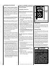
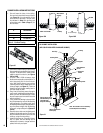
Fireplace Side
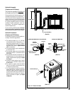
Insulated Chase Construction
Fireplace Facing
The fireplace should be framed using 2" x 3"
(50mm x 75mm) or heavier lumber.
Figure 9 on Page 11 shows the general
framing layout.
Combustible materials must be installed flush
with the fireplace facing. They may not project
out in front of the fireplace. Non-combustible
materials such as brick, stone or ceramic tile,
may project in front of and/or on the fireplace
facing.
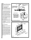
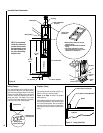
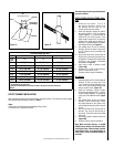
Figure 11 - Facing (Side View)
Insulate Joists
Same As Ceiling
Draft Stops
Firestop
CTDT
Termination
Note: Non-
Combustible
Chase
Flashing
Must Be
Used To
Cover
Chase
Opening
8'
Level
8’
(2.4 m)
Level
Outside
Base
SEE NOTE
Insulation
(Thermal Barrier)
Solid
Continuous
Surface
NOTE: It is recommend-
ed that the chase walls
and floor be insulated in
the same manner, using
the same insulation, as
the rest of the building,
below the attic.
Finished wall
• Must have the same res rating as
adjacent ceiling.
• Must be insulated same as adjacent
ceiling.
• Local code regulation for ceiling
must be applied to the ceiling / floor
separation i.e. firestop, etc.
Ceiling / floor
separation
Flashing
Non-combustible
chase top
Roof support
Attic firestop
FIREPLACE
7’ 4"
(2.2 m)
Min.
7’
(2.1 m)
Min.
1/2” Plywood
Base if required.
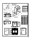
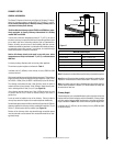
Figure 10
Drywall panel or Equivalent
2" x 3" (50mm x 75mm) Minimum
Fireplace
Spacer
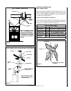
Nailing Flanges
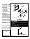
Four nailing flanges are provided to secure
the fireplace to the floor (see figure below).
Bend the nailing flanges down so that each
flange is flush with the floor, then using nails
or screws, secure the fireplace to the floor (2
places each side). The heads of the screws
or nails must be large enough to completely
cover the holes in the nailing flanges.
42”
(1067 mm)
43”
(1092 mm)
43”
(1092 mm)
27-1/2”
(699 mm)
10-5/8”
(270 mm)
33”
(838mm)
42-1/2”
(1080 mm)
17-1/8”
(435 mm)
28-5/16”
(719 mm)
Nailing Flange
(2 places each side)
Unbend to floor
and nail/screw