


25
NOTE: DIAGRAMS & ILLUSTRATIONS ARE NOT TO SCALE.
* The breaker supplying electricity to the fireplace must be turned
off at the electrical panel before any connections are made at the
fireplace.
* The wire supplying the fireplace should be a minimum of 14 gage
and provide 120 Volts at 60 hz.
* The fireplace must be grounded in accordance with local electrical
codes or, in the absence of local codes, with the National Electrical
Code or ANSI/NFPA 70 - latest edition.
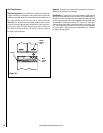
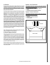
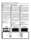
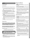
* The electrical box is located at the right rear of the fireplace (see
drawing below). Remove the cover, loosen the wire clamp A and
feed the household supply line through the clamp and retighten
clamp.
* Connect the supply ground wire to the green screw B.
* Remove the wire nut C from the black wire coming from the fireplace
and join this wire to the black supply wire reusing the wire nut.
Repeat for white wire.
* Reinstall the electrical box cover.
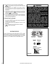
* If a wall-mounted burner on/off switch or thermostat is to be used,
the wires running from the switch or thermostat should be routed
to the left side of the fireplace. The wire should be fed through the
gas line supply hole along the gas line to the valve.
CAUTION: Label all wires prior to disconnection when servic-
ing controls. Wiring errors can cause improper and dangerous
operation.
ATTENTION: Au moment de l'entretien des commandes,
étiquetez tous les fils avant de les débrancher. Des erreurs
de cáblage peuvent entraîner un fonctionnement inadéquat
et dangereux.
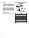
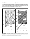
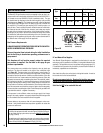
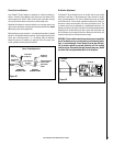
Green (Ground)
Black (Hot)
White (Neutral)
Black
Black
Speed Control
Blower
From Power Source
Snap Switch
(contacts close
when fireplace
is hot)
Blower Wiring Diagram
Wall-Mounted Blower Speed Control
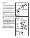
If desired, a wall-mounted blower speed control can be installed. The
breaker suppling electricity to the fireplace must be turned off at the
electrical panel before any connections are made. The loop of wire with
the label attached (E above) may be cut and the wire leads from the wall-
mounted speed control connected to each end of the cut wire.
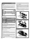
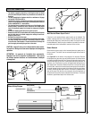
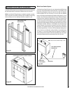
Blower Removal
Disconnect the power supply at the household electrical panel prior to
blower removal. The blower can be accessed through the back wall of
the firebox.
See Figure 29 for the blower wiring diagram, for reference. Remove
the fireplace face, glass door, log set and brick panels. All of these items
are fragile so handle them with care. Remove the two allen head screws
at the left and right rear of the air control panel and lift the panel out. At
the lower rear of the firebox is a piece of angled metal fastened by two
allen head screws at each end. Remove these four screws and the piece
of metal. Next, remove the six allen head screws around the outside of
the panel fastened to the back wall of the firebox. Shift this panel about
an inch to the left and then pull it forward. The blower is fastened to the
back of this panel. Pull the two wire connectors from the terminals on
the blower and remove the blower and panel from the firebox. To reinstall
the blower, repeat these steps in the reverse order.
B
A
E
C
Figure 27
Figure 28
Figure 29
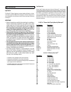
ELECTRICAL CONNECTIONS