


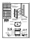

NOTE: DIAGRAMS & ILLUSTRATIONS ARE NOT TO SCALE.
23
Pressure
Regulator
Remove
These
Components
P
S
I
OFF
I
ON
CONTROL
I
G
N
I
T
E
Gas Valve
Assembly
Manifold
Pressure
Test Port
Slotted
Cap
Spring
Adjusting
Screw
Figure 42
Figure 41
Figure 43
Figure 40
Figure 39
Figure 44
All Models
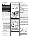
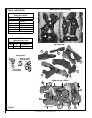
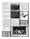
Step 7. (Refer to Figure 38 on Page 22 and
Figure 43)
VERIFY THE PROPER ORIFICE SIZE BE-
FORE INSTALLING IT.
a. Remove the orifice from the manifold and
replace it with the one provided in the kit. Table
8 shows the orifice sizes for natural and pro-
pane models. Figure 43 illustrates the orifice.
Use pipe joint compound or Teflon tape on all
pipe fittings before installing (ensure propane
resistant compounds are used in propane
applications, do not use pipe joint compounds
on flare fittings).
Pilot
Orifice
Pilot
Orifice
Pilot
Assembly
Igniter
Assembly
Retaining
Clip
Flare Nut
When reinstalling the igniter assembly, use
extreme care to prevent damage and break-
age. Do not apply any leverage to the igniter
assembly while restoring the retainer clip to
its original position.
Note: If the igniter is damaged, a replacement kit
is available, order Catalog No. 87L54.
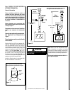
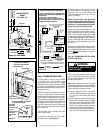
Electronic Appliances
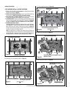
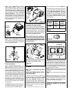
Step 6. Honeywell Electronic Valves - See
Figure 41 and the instructions provided with
the kit. Remove the slotted cap screw, o-ring,
pressure-regulating adjusting screw and spring.
Retain all parts for possible later use. Install
new components from the kit. Black cap and
red spring for propane gas appliances. Silver
cap and stainless steel spring for natural gas
appliances. Before installing the cap, attach
manometer to the manifold side pressure test
fitting and adjust screw until pressure reads
3.5 inches water column (0.87 kPa) for natural
gas, and 10.0 inches water column (2.49 kPa)
for propane gas.
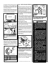
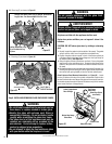
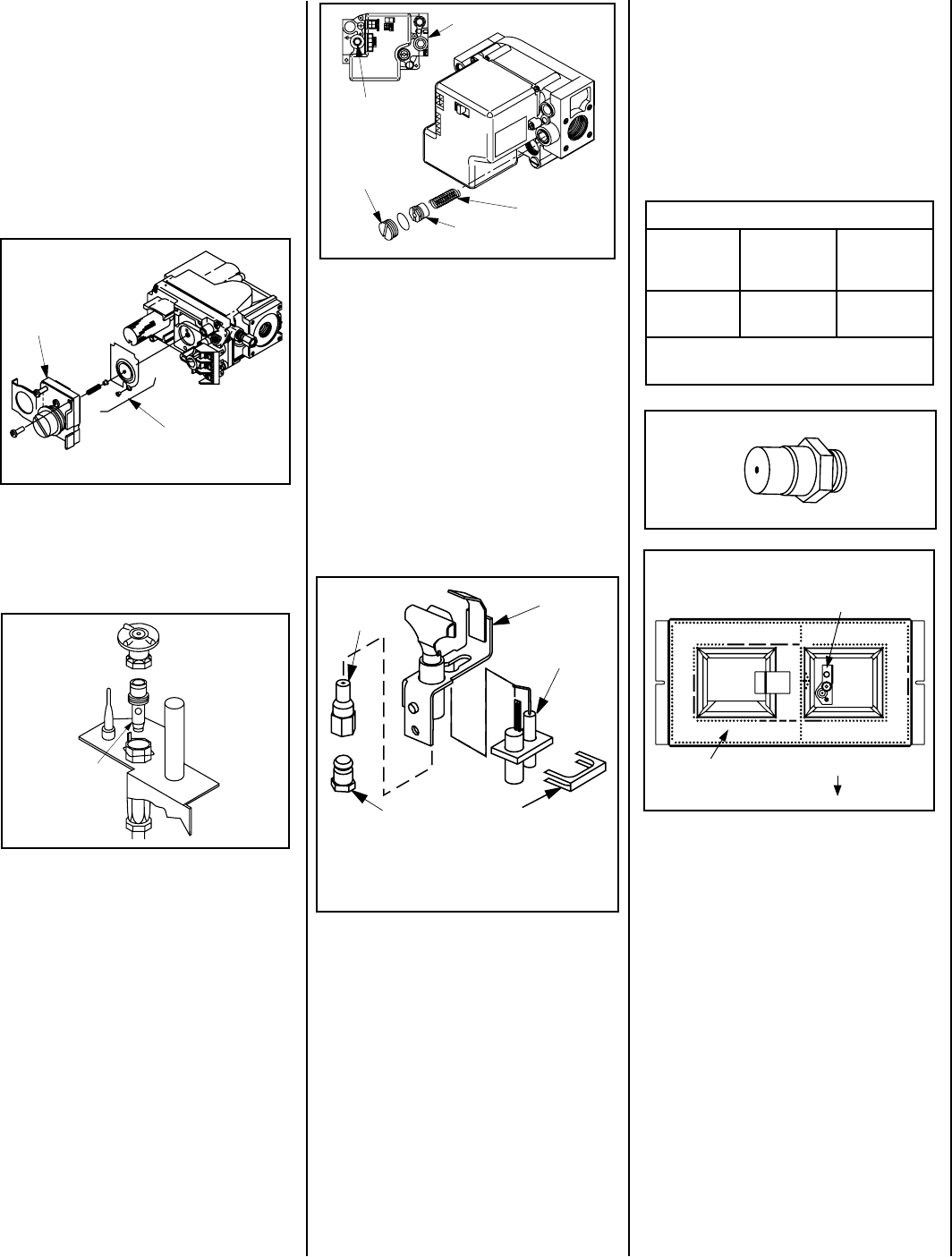
See Figure 42 and replace the pilot orifice as fol-
lows: Remove the igniter assembly retainer clip,
and carefully remove the igniter assembly.
Step 8. Reassemble the remaining components
by reversing the procedures outlined in the
preceding steps. Use pipe joint compound or
Teflon tape on all pipe fittings before installing
(ensure propane resistant compounds are used
in propane applications, do not use pipe joint
compounds on flare fittings).
Step 9. Attach the conversion label provided
in the conversion kit to the rating plate on the
appliance.
Step 10. Turn on gas supply and test for gas
leaks.
Step 11. Attach manometer to the manifold
side pressure test fitting and verify manifold
pressure reads 3.5 inches water column (0.87
kPa) for natural gas, and 10.0 inches water
column (2.49 kPa) for propane gas.
ALWAYS TEST PRESSURES WITH THE VALVE
REGULATOR CONTROL AT THE HIGHEST
SETTING.
Exercise extreme care to prevent damage to
or breakage of the igniter assembly.
Remove the screw securing the pilot assembly
to its mounting bracket. Back off the flare nut
at the end of the pilot gas line to free the pilot
assembly from the gas line. Remove the pilot
orifice and replace it with the one provided with
the conversion kit. Reinstall the pilot assembly
by reversing the steps detailed here.
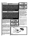
Step 5. Refer to Figure 40 and remove the
pilot hood assembly to access the hexed pilot
orifice. Remove and replace the orifice with
the one provided with the kit.
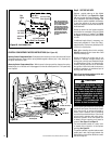
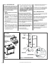
b. Install the burner as shown in Figure 38.
Ensure that the arm of the venturi of the burner
is hooked onto the air shutter adjustment lever
(refer to Figure 38 on Page 22). The primary
air opening can be adjusted by rotating the
adjustment lever from beneath the firebox
floor. Refer to Figure 35 on Page 19 for the
recommended minimum primary air shutter
opening setting.
Pan Burner
BURNER POSITIONING
Valve Access Side
Pilot Assembly
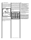
Burner Orifice Sizes (all models)
Elevation
Feet (meters)
Natural
Gas
drill size (inches)
Propane
Gas
drill size (inches)
0 - 4500
(0-1372)
#37 *
(.104")
1.55
mm *
(.061")
* Standard size installed at factory
Table 8
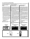
Step 5. Refer to Figure 39 and the instruc-
tions provided with the kit. Using a Torx T20
(with 1/4” shank and center hole), remove and
discard the three pressure regulator mounting
screws. Remove the pressure regulator, spring,
poppet, diaphragm and bushing. Discard all
removed components. Ensure the rubber
gasket installed on the back of the replacement
pressure regulator is properly positioned and
install the new pressure regulator using the new
screws supplied with the kit. Tighten screws
to 25 In. lb. torque.