


NOTE: DIAGRAMS & ILLUSTRATIONS ARE NOT TO SCALE.
20
17
Combustible
Wall
Framing
Combustible
Finished Wall
Materials
Drywall
Bracket/Spacer
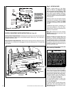
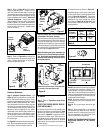
Top of Appliance
Louvers
Top of Door
Frame
Hood must be
installed as shown.
1 in. Min.
(25 mm)
Top
Spacers
Top of Appliance
Radiant panel
Top of Door Frame
Hood must be
installed as shown.
IF OPTIONAL RADIANT
PANELS ARE INSTALLED
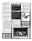
6. Take a smoke producing device and move
it along the bottom edge of the glass door
(where it is cracked open). If smoke is
drawn into the firebox, the vent operation
is adequate.
IF THE SMOKE IS NOT
DRAWN INTO THE FIREBOX, TURN THE
APPLIANCE OFF AND CALL A QUALIFIED
SERVICE TECHNICIAN.
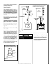
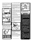
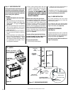
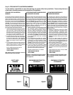
Manual-Reset (safety limit) Spill Switch
This appliance is equipped with a (safety limit)
spill switch that is designed to "trip" and discon-
nect the burner circuit if flue spillage occurs
(because of improper venting of combustion
products or vent blockage). If, during appliance
operation, the burner flame goes out (indepen-
dently of the burner OFF/ON wall switch), it may
be due to the operation of this (safety limit) spill
switch. If this switch "trips" it will need to be
manually reset by pressing the reset button on
switch (see Figure 36).
Procedure to Reset (safety limit) Spill Switch
ALLOW APPLIANCE TO COOL COMPLETELY
BEFORE ACCESSING AND RESETTING
To access the spill switch:
1. Pull off the top louvered panel.
2. Locate and press the red reset button on
the switch (it will click and lock in).
The appliance should then relight and remain
lit. If this does not occur, turn off the appliance
and call a qualified service technician.
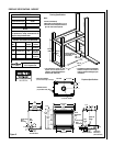
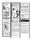
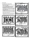
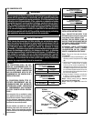
Step 12. HOOD INSTALLATION
All of these appliances must have hoods
installed prior to operating on all sides with
glass enclosure panels.
On all clean face units (with optional radiant
panels), slide the hoods into the slots on the lower
edges of the radiant panel (Figure 37).
FINISHING REQUIREMENTS
(Wall Details)
Complete finished interior wall. To install the
appliance facing flush with the finished wall,
position framework to accommodate the thick-
ness of the finished wall (Figure 37)
See Page 5 for Cold Climate Insulation and
Page 7 for Clearances.
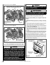
Step 11. VENT OPERATION TEST
A vent operation test is required as part of the
installation to verify that proper venting condi-
tions exist and should be done periodically to
ensure nothing has changed that would affect
proper venting of the appliance.
Procedure:
1. ENSURE APPLIANCE IS OFF (PILOT ONLY)
AND COOL.
2. Open both latches on one of the glass enclo-
sure doors and slightly prop it open at the
bottom (approx. 1/4” gap). See Figure 33
on Page 18.
3. Turn on all the exhaust fans in the dwelling
(and any other appliances which remove
air from the dwelling, such as a furnace or
clothes dryer, etc.).
4. Ensure that all the doors and windows in
the room where the fireplace is located are
closed.
5. Light the appliance (see Lighting Instruc-
tions in Control Compartment or Care and
Operation Instructions Manual). Adjust
flame height to highest setting and operate
for approximately 5-10 minutes. Do not
leave appliance unattended.
SPILL SWITCH
Press Reset
Button on Spill
Switch
Remove Top Louvered
Panel (or optional radiant
panel, if applicable)
Figure 36
Figure 37 - FINISHING REQUIREMENTS