


9
NOTE: DIAGRAMS & ILLUSTRATIONS ARE NOT TO SCALE.
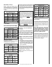
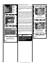
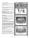
Variable Flame Height Adjustment
( Millivolt Appliances only)
All Millivolt appliances are equipped with a
variable gas control valve. Flame height for
these models may be adjusted through a range
between fixed low and high settings while the
appliance is in operation. Adjust the flame
height as desired after lighting the appliance by
rotating the variable adjustment control knob
(HI/LO) located on the front of the valve (refer
to Figure 2).
Vent Operation Test and Safety Limit
Switch Operation
VENT OPERATION TEST
After appliance installation, perform this vent
operation test to verify that proper venting
conditions exist:
1 - Place unit in its normally-operated condi-
tion, that is, with the glass enclosure panel
in place.
2 - Close all doors and windows in the room.
Turn on all exhaust fans in the house.
3 - Light the appliance.
4 - Wait 15 minutes.
5 - To check for venting action, start by holding
a smoke producing device within an inch
of one edge (side edge, not top or bottom
edge) of the glass enclosure panel. The
smoke should be drawn toward the edge
of the glass enclosure panel. Continue the
test by moving the smoke producing device
along the entire length of both side-edges
of the glass door.
6 - If the smoke is not drawn towards the
edges of the glass door turn off the
appliance and call a qualified service
technician.
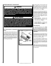
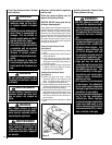
Manual-Reset Safety Limit Switch
This appliance is equipped with a manual reset
blocked flue safety limit switch. Refer to Figure 5
on Page 10 for its location. If, during appliance
operation, the flame goes out (independently of
the burner on/off wall switch), it may be due to
the operation of this safety limit switch. First
allow the appliance to cool. Remove top louver
panel. Then reset the safety limit switch by
pushing the red reset button, located between
the wire terminals, on the back of the switch.
See Detail A of Figure 4 for location.
The appliance should then relight and remain
lit. Reinstall top louver panel. If the appliance
does not relight, turn off the appliance and call
for a qualified service technician.
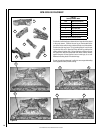
Electronic Appliances -
To light electronic appliances refer to the detailed
lighting instructions found on Pages 26 and
27 of these instructions. Electronic appliance
lighting instructions may also be found on the
pull out lighting instruction labels attached to
the gas control valve.
If your electronic appliance is equipped with
an optional remote wall switch, unit mounted
on/off switch or remote control kit, the appliance
main burner may be turned on and off with the
optional switch.
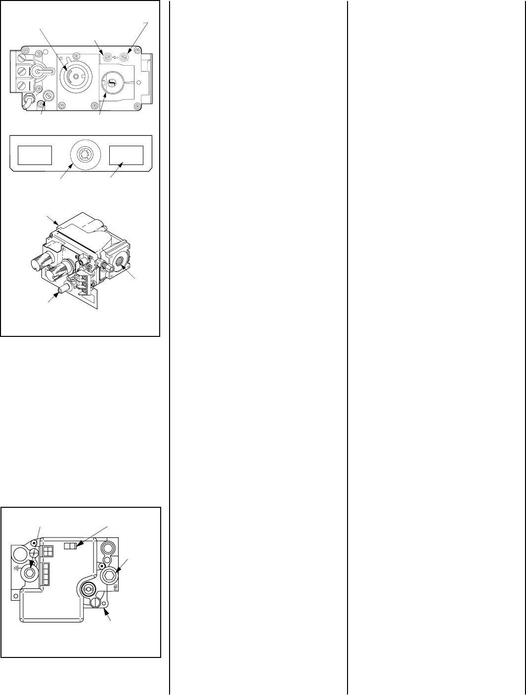
Figure 2 - SIT Millivolt Gas Valve
Figure 3 - Honeywell Electronic Gas Valve
FFO
NI
P
S
I
NO
LORTNOC
GI NTIER
Manifold Pressure
Port
ON / OFF Switch
Inlet
Pressure
Port
Electronic Gas
Control Valve
HI/LO Variable
Flame Height
Adjustment
Manifold Pressure Tap
Inlet Pressure Tap
H
I
L
O
W
H T P T H T P T
P
I
L
O
T
P
I
L
O
T
O
N
t i
O
F
F
IN
OUT
Main Gas Control Knob
OFF/PILOT/ON
Pilot Adjustment
Screw
Piezo Igniter
Optional Burner ON/OFF
Rocker switch location
(one of two places)
Piezo Igniter
Gas
Outlet
Gas
Inlet
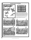
TO REPLACE THE BLOCKED FLUE SAFETY
LIMIT SWITCH
NOTE - This procedure should only be per-
formed by a qualified service technician.
Important - Turn electrical power off before
beginning this procedure.
For steps 1-10 below, refer to Figure 4 on
Page 10 (Details B and C):
1 - Lower the bottom control compartment
access panel. Remove the glass enclosure
panel: open the latch (located in the center
of the unit front opening, under the firebox
floor) securing the glass enclosure panel.
Remove the panel by tilting it outward at
the bottom and lifting it up. Set the door
aside protecting it from inadvertent dam-
age. See Figure 6 on Page 12.
2 - Remove the lintel securing screws (3) and
then remove the lintel. One of the lintel
cabinet top holes is shown in Figure 4
(Detail B).
3 - Remove the scoop securing screws (3)
and then remove the scoop. See Figure
4 (Detail B).
4 - Remove the safety switch bracket securing
screws (2), and pull the switch/bracket
assembly, with low voltage wires attached,
through the side panel slot into the firebox.
See Figure 4 (Detail C).
5 - Replace the switch.
6 - Reinstall the switch/bracket assembly.
7 - Reinstall the scoop and lintel.
8 - Reinstall the glass enclosure panel.
9 - Raise the bottom control compartment
access panel.
10 - The appliance should then relight and
remain lit. If this does not occur, check
unit for a blocked flue condition.