


19
NOTE: DIAGRAMS & ILLUSTRATIONS ARE NOT TO SCALE.
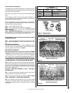
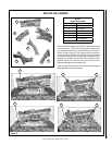
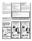
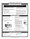
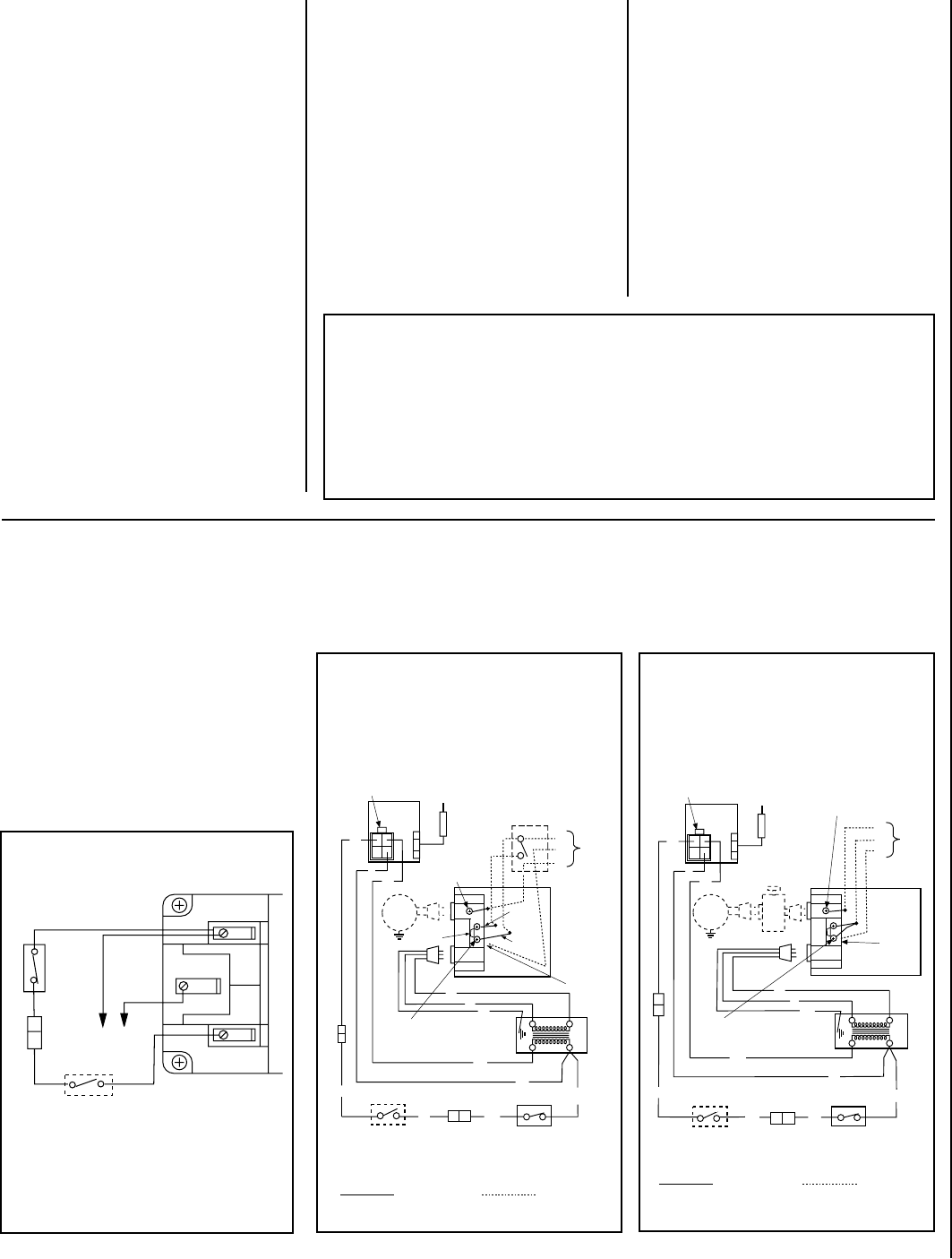
SIT Millivolt Wiring Diagram
If any of the original wire as supplied must be replaced,
it must be replaced withType AWM105°C– 18 GA. wire.
Thermopile
HT
PT
HT
PT
*TWIST WIRES “A” AND “B” TOGETHER TO OPERATE UNIT
SOLELY BY MANIPULATING THE GAS VALVE CONTROL KNOB;
OR CONNECT WIRES TO OPTIONAL ON/OFF SWITCH OR WALL
SWITCH OR THERMOSTAT OR REMOTE CONTROL RECEIVER
TO OPERATE UNIT.
*OPTIONAL ON/OFF SWITCH,
WALL SWITCH, THERMOSTAT
OR REMOTE CONTROL RECEIVER
AB
HCTIWS TIMIL
WT
BK
BK
BK
Schematic Representation Only
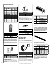
1. If any of the original wire as supplied must be replaced,
1. it must be replaced with T ype A WM 105 °C – 18 GA. wire.
2. 120V , 60Hz – Less than 3 amps.
BK
Junction Box
Tr ansf.
120 V.
24 V
Facto ry Wire d Field Wire d
BL
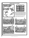
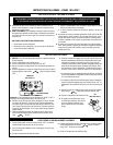
Electronic Wiring Diagram (Honeywell)
Showing the Blower Wiring for the Optional
FBK-100 and FBK-200 Kits
R
W
BL
OPT
BLOWER
G
W
*OPTIONAL
ACCESSOR Y
SWITCH
120
V AC.
BK
W
Gas Va lve
B
R
IGNITER
PILOT
ASSEMBL Y
Break Of f
Ta b
BK
G
*Blower speed control switch is provided in FBK200 blower kit.
Outlet Box
Green Ground
Screw
Hot side of Outlet
Schematic Representation Only
**ON/OFF Switch (Integral
with Gas Va lve )
**Leave the ON/OFF switch, which is integral
with the gas valve, in the ON position.
Red
pigtail
Black
pigtail
White Wire
to Opposite
Side
G
LIMIT SWITCH
OPTIONAL W ALL SWITCH
OR OPTIONAL THERMOS TAT OR
OPTIONAL REMOTE RECEIVER
BK BK
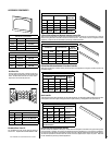
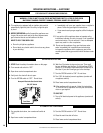
1. If any of the original wire as supplied must be replaced,
1. it must be replaced with Type AWM 105C – 18 GA. wire.
2. 120V, 60Hz – Less than 3 amps.
BK
Junction Box
Transf.
120 V.
24 V
Factory Wired Field Wired
BL
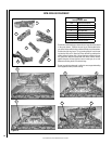
Electronic Wiring Diagram (Honeywell)
Showing the Blower Wiring for the Optional
FBK-250 Kits
R
BL
OPT
BLOWER
G
W
120
VAC.
BK
W
Gas Valve
B
R
IGNITER
PILOT
ASSEMBLY
BK
Outlet Box Green
Ground Screw
Hot side of Outlet
Schematic Representation Only
*ON/OFF Switch (Integral
with Gas Valve)
White Wire
To Opposite
Side
Optional FBK-250
Module
*Leave the ON/OFF switch, which is integral
with the gas valve, in the ON position.
OPTIONAL ON/OFF SWITCH,
WALL SWITCH, THERMOSTAT
OR REMOTE CONTROL RECEIVER
G
W
LIMIT SWITCH
BK
BK
Figure 19
Figure 20
Figure 21
WIRING DIAGRAMS
Wiring diagrams are provided here for reference
purposes only. This information is also provided
on schematics attached directly to the appliance
on a pullout panel located within the control
compartment.
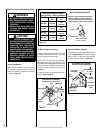
CAUTION: LABEL ALL WIRES
PRIOR TO DISCONNECTION WHEN
SERVICING CONTROLS. WIRING
ERRORS CAN CAUSE IMPROPER
AND DANGEROUS APPLIANCE
OPERATION.
WARRANTY
Your gas appliance is covered by a limited twenty
year warranty. You will find a copy of the war-
ranty accompanying this manual. Please read
the warranty to be familiar with its coverage.
Retain this manual. File it with your other docu-
ments for future reference.
REPLACEMENT PARTS
A complete parts list is found at the end of
this manual. Use only parts supplied from the
manufacturer.
With proper care and maintenance, your appli-
ance will provide many years of enjoyment. If
you should experience any problem, first refer
to the troubleshooting guide in this manual. If
problem persists, contact your Lennox Hearth
Products dealer or distributor.
Normally, all parts should be ordered through
your Lennox Hearth Products distributor or
dealer. Parts will be shipped at prevailing prices
at time of order.
When ordering repair parts, always give the
following information:
1. The model number of the appliance.
2. The serial number of the appliance.
3. The part number.
4. The description of the part.
5. The quantity required.
6. The installation date of the appliance.
If you encounter any problems or have any
questions concerning the installation or ap-
plication of this system, please contact your
dealer or distributor.
LENNOX HEARTH PRODUCTS
1508 Elm Hill Pike, Suite 108
Nashville, TN 37210
visit us at www.Lennox.com
1-800-9-LENNOX
PRODUCT REFERENCE INFORMATION
We recommend that you record the following
important information about your fireplace.
Please call Lennox Hearth Products for the
phone number of your nearest Lennox Hearth
Products dealer who will answer your questions
or address your concerns.
Your Fireplace's Model Number ___________________________________________
Your Fireplace's Serial Number ___________________________________________
The Date On Which Your Fireplace Was Installed ______________________________
The Type of Gas Your Fireplace Uses _______________________________________
Your Dealer's Name ___________________________________________________
ATTENTION : AU MOMENT DE L'ENTRETIEN DES COMMANDES, ÉTIQUETEZ
TOUS LES FILS AVANT DE LES DÉBRANCHER. DES ERREURS DE CÁBLAGE
PEU-VENT ENTRAÎNER UN FONCTIONNEMENT INADÉQUAT ET DANGEREUX.