


8
NOTE: DIAGRAMS & ILLUSTRATIONS ARE NOT TO SCALE.
*Note: 3 in. (75 mm) above any horizontal/inclined vent component.
**Note: See Page 9, Step 1 for clearance requirements to the nailing
flange located at each side of the unit and any screw heads adjacent to it.
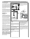
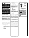
The appliance should be mounted on a fully supported base extending
the full width and depth of the unit. The appliance may be located on
or near conventional construction materials. However, if installed on
combustible materials, such as carpeting, vinyl tile, etc., a metal or wood
barrier covering the entire bottom surface must be used.
Wall Finishes / Surrounds / Mantels
Note: Combustible wall finish materials and/or surround materials must
not be allowed to encroach the area defined by the appliance front face
(black sheet metal). Never allow combustible materials to be positioned
in front of or overlapping the appliance face. See Figure 6 and Figure
43 on Page 26.
Non-combustible materials, such as surrounds and other appliance trim,
may be installed on the appliance front face with these exceptions: they
must not cover any portion of the removable glass panel.
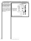
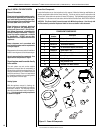
Vertical installation clearances to combustible mantels vary according
to the depth of the mantel (see Figure 5). Mantels constructed of non-
combustible materials may be installed at any height above the appliance
opening.
NOTE: We recommend the use of high temperature paint (rated 175° F
or higher) on the underside of the mantel.
MINIMUM CLEARANCES TO COMBUSTIBLES
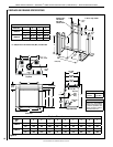
Appliance And Vent Clearances
The appliance is approved with zero clearance to combustible materials
on all sides (as detailed in Table 5), with the following exception: When
the unit is installed with one side flush with a wall, the wall on the
other side of the unit must not extend beyond the front edge of the
unit. In addition, when the unit is recessed, the side walls surrounding
the unit must not extend beyond the front edge of the unit (see Figure
2 on Page 5).
5 (127)
8-1/4
(209)
14
(356)
12 (305)
19
(483)
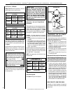
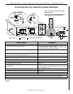
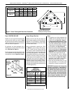
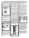
Figure 6 - Minimum Distance to Unprotected Side Wall
Top View of
Fireplace
45
o
Protected wall shown in white
Inches (millimeters)
Combustible materials may
project beyond one side
of the fireplace opening
as long as they are kept
within the shaded areas
illustrated here.
Combustible Materials
Allowed In Shaded Area
“Safe Zone”
Combustible Walls
shown in dark gray
At 14" minimum side
wall clearance, a
combustible wall
can project to any
length.
At 8-1/4" side wall
clearance, a com-
bustible wall can
project 12"
17 (432)
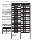
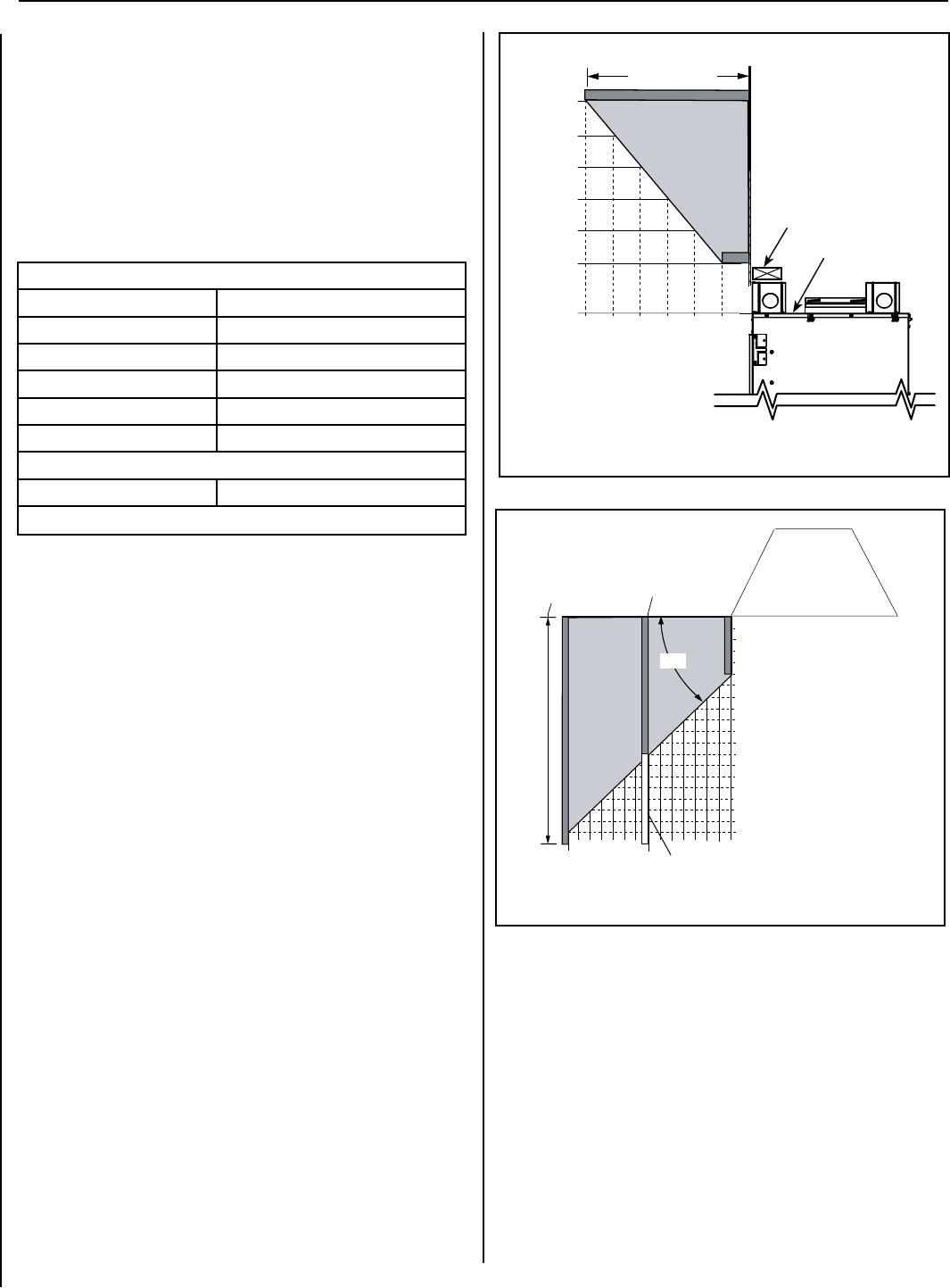
Figure 5 - Minimum Mantel Clearances
8 (203)
2
(51)
4
(102)
6
(152)
8
(203)
10
(254)
12
(305)
10 (254)
14 (356)
18 (457)
16 (406)
12 (305)
Top of
Appliance
inches (millimeters)
Mantel Depth
Header
7 (178)
9 (229)
11 (279)
13 (330)
15 (381)
17 (432)
12 (305)
10 (254)
8 (203)
6 (152)
4 (102)
7
(178)
17
(432)
15
(381)
13
(330)
2 (51)
9
(229)
11
(279)
Fireplace
(side view)
Distance from top of
appliance to bottom
of mantel
LENNOX HEARTH PRODUCTS • MONTEBELLO
®
POWER VENT DV GAS FIREPLACES (LSM40/45EN-PV) • INSTALLATION INSTRUCTIONS
APPLIANCE MINIMUM CLEARANCES* Inches (millimeters)
Sides 1/2 (13), 0 (0) Spacers **
Top Spacers 0 (0)
Floor 0 (0)
Back 1/2 (13), 0 (0) Spacers
Bottom of Appliance To Ceiling 69 (1743)
Vent 3 (76)
Top* / 1 (25.4) Sides & Bottom
SERVICE CLEARANCES Feet (meters)
Front 3 feet (0.9 meters)
Table 5