


18
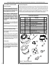
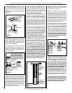
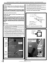
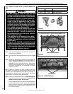
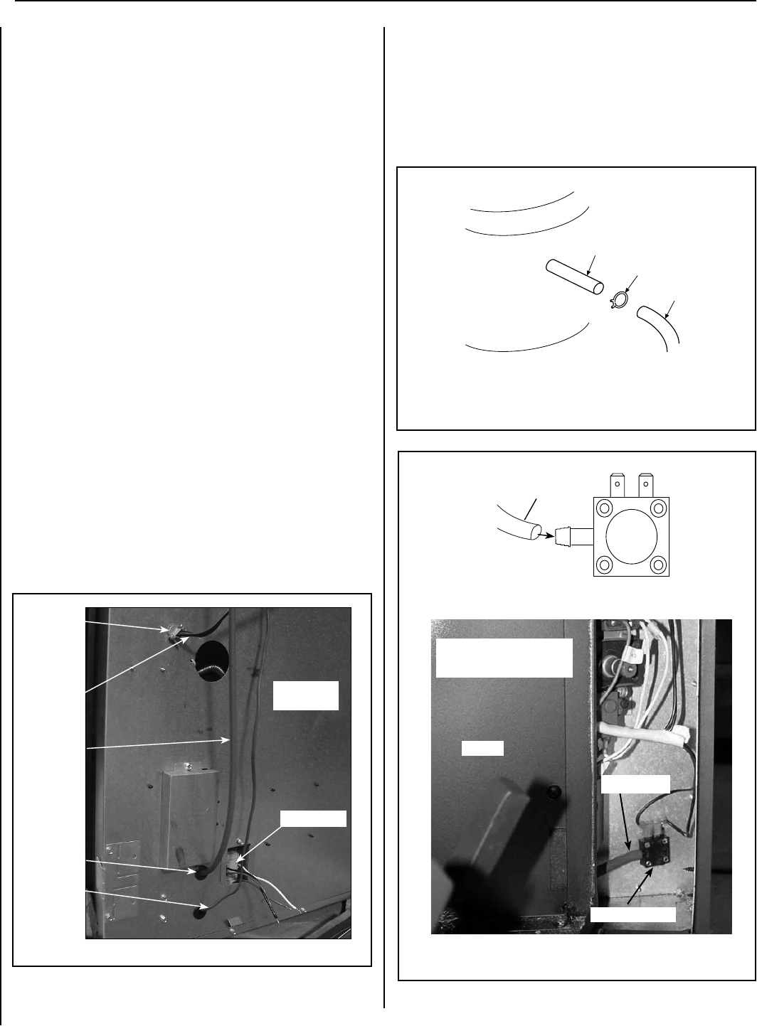
Figure 21A - Vacuum Hose Connection To Probe
Step 4. FIELD WIRING
CAUTION: Label all wires prior to disconnection when servic-
ing controls. Wiring errors can cause improper and dangerous
operation.
ATTENTION: Au moment de l'entretien des commandes, étiquetez
tous les fils avant de les débrancher. Des erreurs de cáblage
peu-vent entraîner un fonctionnement inadéquat et dangereux.
Verify proper operation after servicing.
S'assurer que l'appareil fonctionne adé-quatement une fois
l'entretien terminé.
CAUTION: Ground supply lead must be connected to the wire
attached to the green ground screw located on the outlet box.
See Figures 26 and 27 on Page 20. Failure to do so will result
in a potential safety hazard. The appliance must be electrically
grounded in accordance with local codes or, in the absence of
local codes, the National Electrical Code, ANSI/NFPA 70-latest
edition.
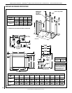
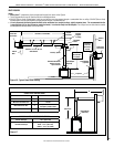
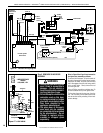
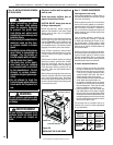
Route Wiring
NOTE: Electrical wiring must be performed by a qualified electrician.
• Install the strain relief in the hole provided on the right side of replace
for the electrical wiring (refer to Figure 20).
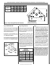
Standard Instruction (For use when access to the termination is dif-
cult because of height or other reasons).
• Locate a locally procured electrical junction box within reach of the
termination wiring pigtail (refer to Figure 22 on Page 19) and route
the pigtail to the junction box as the termination is installed.
• Route 14 gauge AWG grounded Romex wiring (not provided) from
the replace to the just installed junction box close to the termina-
tion. Ensure the wiring is safety plated to prevent damage by framing
nails and finish drywall screws. Route the wire into the lower control
compartment and cut to length before installing the terminals. Install
provided wiring hardware on the ends of the Romex wire.
14 Gage
Grounded
Romex
Strain
Relief
Vacuum
Hose
Snap
Bushing
Wall Switch
Harness
Junction Box
Figure 20
Right Side
of Fireplace
Probe (1 *)
Hose Clamp (7 *)
Vacuum Hose (2 *)
* See Figure 11 on Page 12
Adaptor Assembly
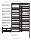
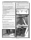
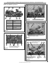
Figure 21B - Vacuum Hose Connection To Pressure Switch
Pressure Switch
Pressure Switch
Vacuum Hose
Firebox
Pressure switch is located
behind the panel on the right
side of firebox
Vacuum Hose
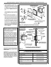
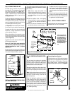
• Refer to Figure 24 on Page 19 and install the electrical hardware
on the ends of the Romex wiring. Male terminals on the Black and
White wires, and ring terminals on the ground wire.
• Using standard electrical practices and the terminals provided, con-
nect the three wires of the Romex cable to the termination pigtail
within the Electrical junction box. Ensure ground.
• The replace end of the Romex will be addressed in Connecting The
Power Vent To The Fireplace Control System.
NOTE: DIAGRAMS & ILLUSTRATIONS ARE NOT TO SCALE.
LENNOX HEARTH PRODUCTS • MONTEBELLO
®
POWER VENT DV GAS FIREPLACES (LSM40/45EN-PV) • INSTALLATION INSTRUCTIONS