


14
NOTE: DIAGRAMS & ILLUSTRATIONS ARE NOT TO SCALE.
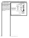
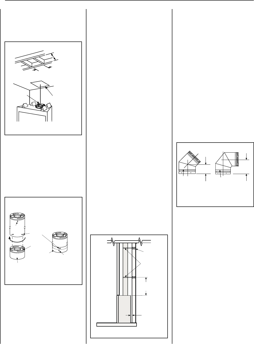
Figure 12
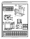
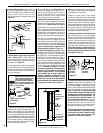
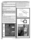
A. Frame ceiling opening - Use a plumb line
from the ceiling above the appliance to locate
center of the vertical run. Cut and/or frame an
opening, 10-1/2" x 10-1/2" (267 mm x 267
mm) inside dimensions, about this center mark
(Figure 12).
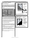
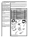
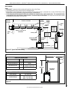
Figure 13
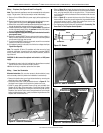
Align the dimple (four places) of the
upper vent section with the opening
of the locking incline channel on
the lower vent section or appliance
collar. Twist vent component clock-
wise to engage and seal until arrow
and dimple align.
Dimple
Locking Incline
Channel
Connected Vent
Sections
Arrow
Arrow
Adaptor on Appliance Collar
or Vent Section
B. Attach adaptor (with probe) to appliance
collar. Secure Vent™ SV4.5 direct-vent
system components are unitized concentric
pipe components featuring positive twist lock
connections (see Figure 13).
All of the appliances covered in this document
are fitted with collars having locking inclined
channels. The dimpled end of the adaptor fits
over the appliance collar to create the positive
twist lock connection.
10-1/2" Min.
(267 mm)
Ceiling Framing
Plumb Bob
10-1/2" Min.
(267 mm)
To attach a vent component to the adaptor on
appliance collar, align the dimpled end over the
adaptor collar, adjusting the radial alignment
until the four locking dimples are aligned with the
inlet of the four inclined channels on the collar
(refer to Figure 13). Push the vent component
against the collar until it fully engages, then twist
the component clockwise, running the dimples
down and along the incline channels until they
seat at the end of the channels.
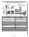
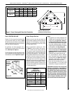
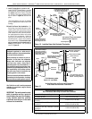
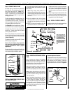
Note - Proper venting support is very important.
The weight of the vent must not be supported
by the fireplace in any degree.
Support the vertical portion of the venting
system every 8 feet (2.4 m) above the replace
vent outlet. One method of support is by utiliz-
ing field provided support straps (conventional
plumber's tape). Secure the plumber's tape to
the framing members with nails or screws. Strap
the tape around the vent, securing the ends of
the tape to the framing. If desired, sheet metal
screws #6 x 1/2" length may be used to secure
the support straps to the vent pipe.
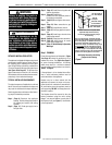
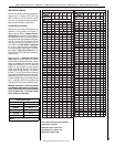
F. Change vent direction to horizontal/inclined
run - At transition from or to a horizontal/in-
clined run, install the SV4.5 E45 and SV4.5 E90
elbows in the same manner as the straight vent
sections. The elbows feature a twist section to
allow them to be routed about the center axis
of their initial collar section to align with the
required direction of the next vent run element.
Twist elbow sections in a clockwise direction
only so as to avoid the possibility of unlocking
any of the previously connected vent sections
(see Figures 13 and 15).
The unitized design of the Secure Vent com-
ponents will engage and seal both the inner
and outer pipe without the need for sealant or
screws. If desired a #6 x 1/2" screw may be
used at the joint, but it is not required as the
pipe will securely lock when twisted.
C. Attach vent components to each other - Other
vent sections may be added to the previously
installed section in accordance with the require-
ments shown in Figures 16 and 17 on Page 15.
To add another vent component to a length of
vent run, align the dimpled end over the inclined
channel end of the previously installed section,
adjusting the radial alignment until the four
locking dimples are aligned with the inlets of
the four incline channels of the previous section.
Push the vent component against the previ-
ous section until it fully engages, then twist
the component clockwise running the dimples
down and along the incline channels until they
seat at the end of the channels. This seating
position is indicated by the alignment of the
arrow and dimple as shown in Figure 13.
D. Install firestop/spacer at ceiling - When
using Secure Vent, use SV4.5VF restop/spacer
at ceiling joists. If there is living space above
the ceiling level, the restop/spacer must be
installed on the bottom side of the ceiling. If
attic space is above the ceiling, the restop/
spacer must be installed on the top side of the
joist. Route the vent sections through the framed
opening and secure the firestop/spacer with
8d nails or other appropriate fasteners at each
corner. Remember to maintain 1" (25 mm)
clearance to combustibles, framing members,
and attic or ceiling insulation when running
vertical chimney sections. Attic insulation
shield (H3907) may be used to obtain the
required clearances indicated here. See
installation accessories on Page 28. The gap
between the vent pipe and a vertical firestop
can be sealed with non-combustible caulking.
E. Support the vertical vent run sections -
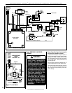
Figure 15
7-5/8”
(194 mm)
4-13/16
(122 mm)
Swivel Joint
(360° swivel)
SV4.5E45
45° Elbow)
Swivel Joint
(360° swivel)
SV4.5E90
90° Elbow)
(206 mm)
8-1/8"
G. Continue installation of horizontal/inclined
sections - Continue with the installation of the
straight vent sections in horizontal/inclined run
as described in Step C. Install support straps
every 3' (914 mm) along horizontal/inclined vent
runs using conventional plumber’s tape (see
Page 15, Figure 16). It is very important that
the horizontal/inclined run be maintained in a
straight (no dips), slightly elevated plane. The
recommended incline is approximately 1/4"
per foot (20 mm per meter) horizontal, in a
direction away from the fireplace. The rise per
foot run ratios that are smaller are acceptable all
the way down to at or near level. Use a carpen-
ter’s level to measure from a constant surface
and adjust the support straps as necessary.
It is important to maintain the required clear-
ances to combustibles: 1" (25 mm) at all sides
for all vertical runs; and 3" (76 mm) at the top,
1" (25 mm) at sides, and 1" (25 mm) at the
bottom for all horizontal/inclined runs.
Figure 14
Blocking
Support Straps
(Plumber's
tape)
8 feet (2.4 m)
Maximum
1/2 inch (13
mm) minimum
clearance to
combustibles
LENNOX HEARTH PRODUCTS • MONTEBELLO
®
POWER VENT DV GAS FIREPLACES (LSM40/45EN-PV) • INSTALLATION INSTRUCTIONS