


17
NOTE: DIAGRAMS & ILLUSTRATIONS ARE NOT TO SCALE.
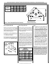
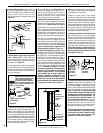
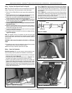
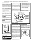
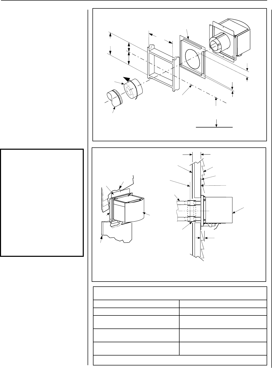
L. Install Firestop/Spacer at exterior wall -
Install SV4.5HF Firestop/Spacer, provided
with the power vent kit, over the opening at
the exterior side of the framing, long side
up, with the 3 inch spacer clearance at the
top as shown in Figure 18, and nail into
place.
(The Firestop/Spacer may also be installed
over the opening at the interior side of the
framing).
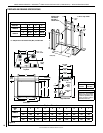
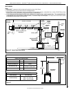
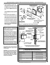
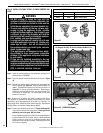
M. Install the Power Vent termination - For
the last step, from outside the exterior wall,
slide the collars of the termination onto the
adaptor (the outer inside the outer and the
inner outside the inner) until the termina-
tion seats against the exterior wall surface
to which it will be attached. Orient the
housing of the termination with the arrow
pointed upwards. Secure the termination
to the exterior wall. The termination must
not be recessed into the exterior wall or
siding by more that the 1-1/4” (32 mm) as
shown in Figure 19.
Siding
Stucco
1-1/4" Maximum Recess of
the Square Termination into
Exterior Finishing Material
Exterior Surface of
Framing
6 in. to 9-1/4 in.
(152 to 235 mm)**
Exterior Surface of Siding
Interior Surface of
Finished Wall
Maximum wall thickness
9-1/4 in.(235 mm)**
Power Vent
Termination
Maximum Extent of Vent Run
Sections Relative to Exterior
Surface of Framing
Last Vent Section.
Use Telescopic Vent
Section (SV4.5LA),
If Necessary
Adapter
SV4.5RCH
Venting Connection and Exterior Wall Recessing
of the Power Vent Horizontal Termination
*Use silicone caulking to
seal the top and sides of
the termination, up to the
underlayment, stucco, or
masonry wall surface.
Power Vent
Termination
*Caulk
*Caulk
Figure 18 - Installing Power Vent Horizontal Termination
Firestop/Spacer (SV4.5HF) shown
on the exterior side of the wall. It
may also be installed on the
interior side.
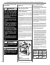
Power Vent
Termination
7"
(178)
5-1/8"
(130 mm)
12-1/8"
(308 mm)
Note: Centerline of Vent Piping is
NOT the Same as the Centerline of
the Frame Opening.
6 to 48 inch Vent Section,
Telescopic vent section,
Elbow or Appliance Collar
Base of Appliance
3"
(76 mm)
1"
(25.4 mm)
Adapter
SV4.5RCH
10-1/2"
(267 mm)
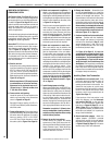
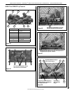
The Power Vent termination has been
designed to perform in a wide range of
weather conditions. Our terminations meet
or exceed industry standards.
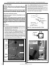
When selecting the location of your ter-
mination, do not place the termination
where water from eaves and adjoining
roof lines may create a heavy flow of
cascading water onto the terminations. If
the termination must be placed where the
possibility of cascading water exists, it is
the responsibility of the builder to direct
the water away from the termination cap
by using gutters or other means.
Take care to carefully follow the Installation
Instructions for the termination, including
the use of silicone caulking where required.
Figure 19
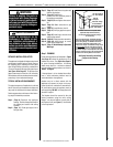
IMPORTANT: The vent termination is hot
while in operation and for a period of
time following the use of the fireplace.
Young children should be carefully
supervised when they are in the same
area as a hot termination.
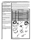
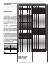
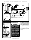
Venting Components Required for Various Exterior
Wall Thicknesses, When Using The Power Vent Termination
Vent Components Required Exterior Wall Thickness - inches (mm)
Termination Kit Only 6 to 9-1/4 (152 to 235)
Termination Kit and 6 In. Vent Section
(SV4.5L6)
10-3/4 to 14 (273 to 356)
Termination Kit and 12 in. Vent Section
(SV4.5L12)
16-3/4 to 20 (426 to 508)
Termination Kit and Telescopic Section
(SV4.5L12)
11-3/4 to 20 (299 to 508)
Table 8
See Table 8 as an aid in venting component
selection for a particular range of exterior
wall thicknesses.
See Figure 8 on Page 10 for Minimum
Distance to Base of Appliance
LENNOX HEARTH PRODUCTS • MONTEBELLO
®
POWER VENT DV GAS FIREPLACES (LSM40/45EN-PV) • INSTALLATION INSTRUCTIONS
**For thicknesses greater
than 9-1/4”, see Table 8