


6
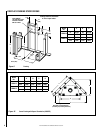
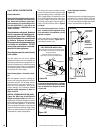
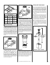
Unit Being Secured by Its Nailing
Flanges to the Framing
Figure 6
Step 1. (Page 6) Construct the appliance fram-
ing. Position the appliance within the framing
and secure with nailing brackets.
Step 2. (Page 6) Route gas supply line to the
right side of the appliance.
Right Side
Front Corner
Of Fireplace
Framing
6-1/4”
(159 mm
)
19-5/8”
(498 mm
)
3"
(76 mm)
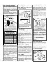
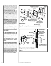
Termination Kit
Combustible Projection
greater than 2-1/2 inches in length
Horizontal Vent Termination Clearances
Combustible Projection
2-1/2 inches or less in length
24"
(610 mm)
Ventilated Or
Unventilated Soffit
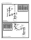
Unit Being Secured by Its Nailing
Flanges to the Framing
Note: The nailing flanges
, combustible members
and screw heads locat
ed in areas directly ad
jacent
to the
nailing flanges, are
EXEMPT from the 1/2”
clearance to combustible requirements for th
e
firebox outer wra
pper
. Combustible framing
may be
in
direct contact with
t
he nailing flanges and
m
ay
be loca
ted closer than 1/2” fr
om screw heads and
the firebox
wrapper in areas adjace
nt to the nailing
flanges. Frame th
e
opening to the exact dimens
ions
specified in the framing det
ails of this manual.
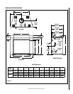
Use T
op Flange For
1/2” Thick Dr
ywal
l
Use Bottom Flange Fo
r
5/8” Thick Dr
ywal
l
Front Of
Fireplace
Use Center Flange
For Flush Mount
Left Side Front Co
rner of Fireplace Shown
(R
ight Side Requirements the
S
ame)
Unit Being Secured By Its Nailing Flanges
To The Framing
Figure 5 - Side Elevation View
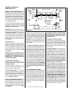
Figure 7
Figure 4
the appliance is to be elevated above floor
level, a solid continuous platform must be
constructed.
Headers may be in direct contact with the
appliance top spacers but must not be sup-
ported by them or notched to fit around them.
All construction above the appliance must be
self supporting, DO NOT use the appliance for
structural support.
The fireplace should be secured to the side
framing members using the unit's nailing
flanges - one top and bottom on each side of
the fireplace front. See Figure 6. Use 8d nails
or their equivalent.
VENT TERMINATION CLEARANCES
These instructions should be used as a guide-
line and do not supersede local codes in any
way. Install vent according to local codes,
these instructions, the current National Fuel
Gas Code (ANSI-Z223.1) in the USA or the
current standards of CAN/CGA-B149.1 and
-B149.2 in Canada.
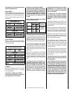
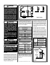
Vertical Vent Termination Clearances
Terminate single vent caps relative to building
components according to Figure 4.
See Figure 27 on Page 16 for the recess allowances, into
exterior walls, of the square horizontal terminations.
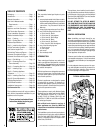
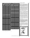
Termination Heights For Vents
Above Flat Or Sloped Roofs
Ref. NFPA 54 / ANSI Z223.1, 7.6
Roof Pitch * Feet * Meters
Flat to 6/12 1.0 0.3
6/12 to 7/12 1.25 0.38
7/12 to 8/12 1.5 0.46
8/12 to 9/12 2.0 0.61
9/12 to 10/12 2.5 0.76
10/12 to 11/12 3.25 0.99
11/12 to 12/12 4.0 1.22
The vent / air intake termination clearances
above the high side of an angled roof is as
shown in the following chart:
12
X
Roof Pitch is X/12
2 FT
MIN.
2 FT MIN.
Lowest
Discharge
Opening
H*
*H = MINIMUM HEIGHT FROM ROOF TO
LOWEST DISCHARGE OPENING OF VENT
TERMINATION HEIGHTS FOR VENTS ABOVE
FLAT OR SLOPED ROOFS
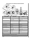
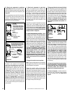
Horizontal Overhang
Vertical
Wall
Vent
Termination
Storm Collar
Concentric
Vent Pipe
Flashing
1 inch (25.4 mm) Minimum
Clearance to Combustibles
Terminate multiple vent terminations accord-
ing to the installation codes listed at the top
of this Page.
Horizontal Vent Termination Clearances
The horizontal vent termination must have
a minimum of 3" (76 mm) clearance to any
overhead combustible projection of 2-1/2" (64
mm) or less. See Figure 5. For projections
exceeding 2-1/2" (64 mm), see Figure 5. For
additional vent location restrictions refer to
Figure 8 on Page 7.
TYPICAL INSTALLATION SEQUENCE
The typical sequence of installation follows,
however, each installation is unique resulting
in variations to those described.
See the Page numbers references in the follow-
ing steps for detailed procedures.
Step 3.
(Page 10) Install the vent system and
exterior termination.
Step 4. (Page 19) Field Wiring
a. Millivolt and Electronic Appliances – The
operating control switch is factory installed.
b. Electronic Appliances – Connect 120 Vac
electrical power to the appliance receptacle.
Step 5. (Page 20) Remove glass door frame
assembly.
Step 6. (Page 20) Make connection to gas
supply.
Step 7. (Page 20) Install ceramic panels, logs
and glowing embers.
Step 8. (Page 21) Checkout appliance opera-
tion.
Step 9. (Page 21) Install glass door frame
assembly.
Step 10. (Page 21) Adjust burner to ensure
proper flame appearance.
DETAILED INSTALLATION STEPS
The appliance is shipped with all gas controls
and components installed and pre-wired.
Remove the shipping carton, exposing the
front glass door. Using a Phillips screwdriver,
unfasten two (2) screws located at the top of the
glass frame (see Figure 37). Tilt the top of the
glass frame away from the unit. Lift it carefully
off the bottom door track and set the door aside,
protecting it from inadvertent damage.
Step 1. FRAMING
Frame these appliances as illustrated in Figure
9 on Page 8, unless the appliance is to be
installed in a corner. See Figure 10 on Page
8 for corner framing installations. All framing
details must allow for a minimum clearance to
combustible framing members as shown in
Table 5 on Page 5.
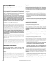
Step 2. ROUTING GAS LINE
Route a 1/2" (13 mm) gas line along the inside
of the right side framing as shown in Figure
7. Gas lines must be routed, constructed and
made of materials that are in strict accordance
with local codes and regulations.
All appliances are factory-equipped with a
flexible gas line connector and 1/2 inch shutoff
valve. (See Step 5 on Page 20).